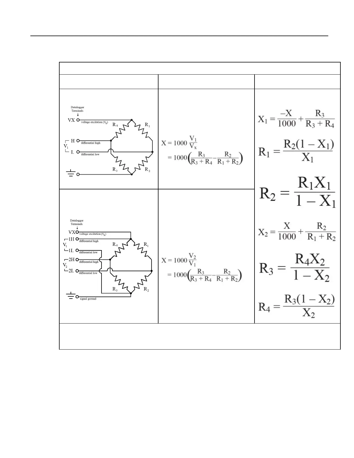
Table 71. Resistive-Bridge Circuits with Voltage Excitation
Resistive-Bridge Type and
Circuit Diagram
CRBasic Instruction and
Fundamental Relationship
Other
Relationships
Full-Bridge
1,3
CRBasic Instruction: BrFull()
Fundamental Relationship
2
:
These relationships apply to BrFull() and
BrFull6W().
Six-Wire Full-Bridge
1
CRBasic Instruction: BrFull6W()
Fundamental Relationship
2
:
1
Key: V
x
= excitation voltage; V
1
, V
2
= sensor return voltages; R
f
= "fixed", "bridge" or "completion" resistor; R
s
= "variable" or "sensing" resistor.
2
Where X = result of the CRBasic bridge measurement instruction with a multiplier of 1 and an offset of 0.
3
See the appendix Resistive Bridge Modules (p. 647) for a list of available terminal input modules to facilitate this measurement.
340

 Loading...

