114Service Manual – CS7010™ 24 - Electrical System
Common 2-Pole Connectors (continued)
1
X125 Left Side Broom
Pin Color Name
1 GRN-GRY
K2B+
2 WHT-BRN Control
X127 Left Headlight
Pin Color Name
1 BLK-WHT KSI
2 BRN Control
X132 Side Broom Actuator
Pin Color Name
1 RED-BRN Control A
2 TAN-BLU Control B
X133 Right Side Broom
Pin Color Name
1 GRN-GRY
KB+
2 BLK-WHT Control
X135 Dump Door Closed Switch
Pin Color Name
1 GRN-ORG Signal
2 BLU-BLK B-
X136 Right Headlight
Pin Color Name
1 BLK-WHT KSI
2 BRN Control
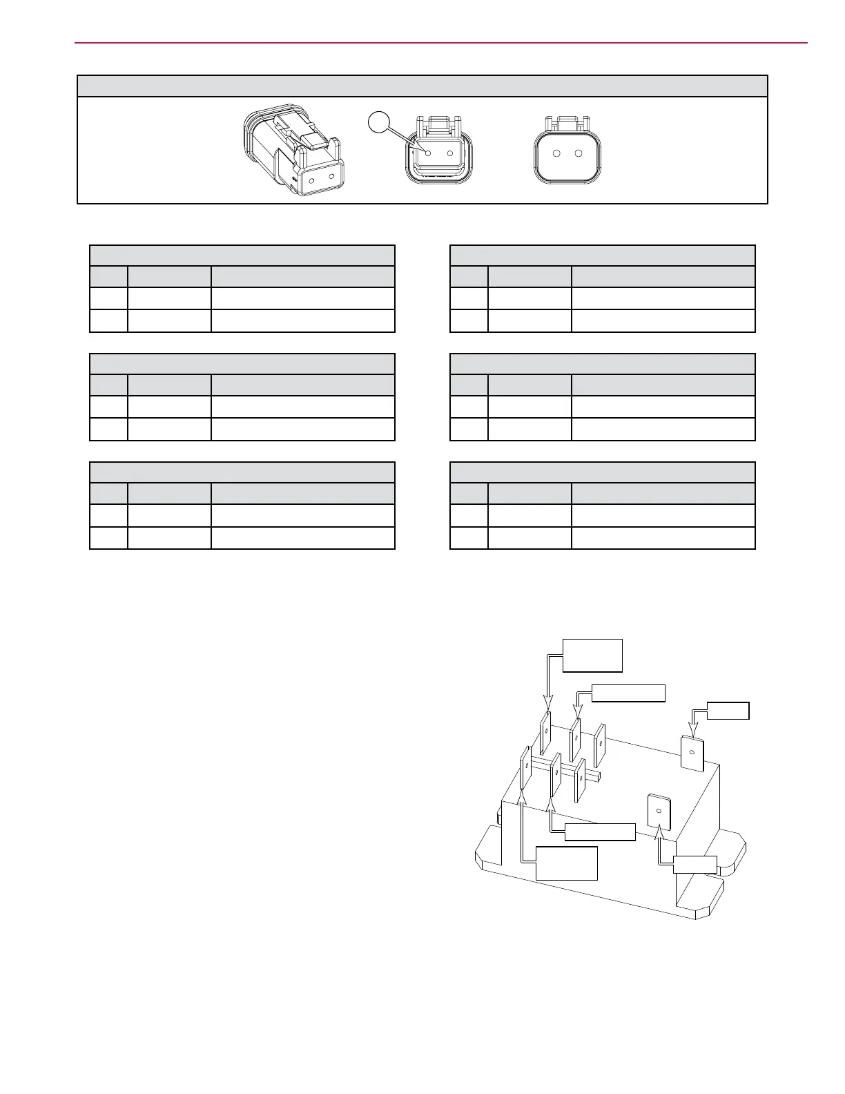
K1 and K5 Relays
The K1 and K5 relays are Single-Pole, Double-Throw (SPDT)
box relays. They have two sets of contacts (1 & 2) that
close when the coil is energized. When the coil is energized,
common 1 connects to Normally Open 1; and Common 2
connects to Normally Open 2.
Both sets of contacts are the same and can be interchanged.
Just note that set 1 is isolated from set 2, so they operate as
2 independent switches.
The coil operates at 36 volts, and does not have polarity. So
the wires on A and B can be reversed.
The two unlabeled/unused terminals are Normally Closed
contacts that open when the relay is energized.
Coil B
Coil A
Common 2
Normally
Open 2
Common 1
Normally
Open 1