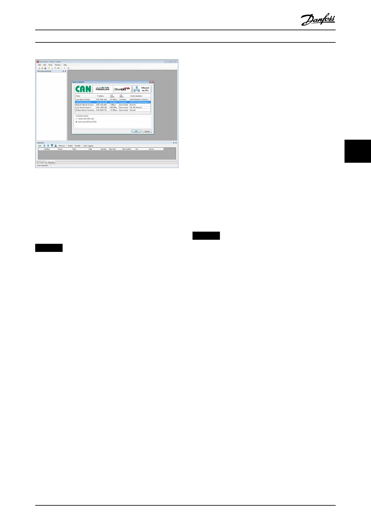
Illustration 5.6 Connect To Network Window (Ethernet
POWERLINK
®
)
STEP 3: Scan for devices
1. After verifying that the ISD Toolbox is connected
to the selected network, click on the Scan for
Devices icon in the toolbar to trigger the device
scan procedure.
NOTICE
If connected to an Ethernet POWERLINK
®
network in
cyclic mode, select the scan range (minimum and
maximum IDs) in the next window to reduce the time
needed for scanning. In all other cases, the complete ID
range is scanned.
2. When the scan is complete, a list of available
devices is shown in the Select Devices window.
Select which devices to add to the Device
Environment and click on OK.
3. All selected devices appear in the Device
Environment window and automatically go online
(indicated by a glowing light bulb next to each
device name).
The ISD Toolbox software can be used to optimize the
control loop parameters. For this purpose, determine the
inertia of the servo drive and the external load by using
the inertia measurement within the drive control (see
section Inertia Measurement Mode tab in chapter 5.7.4 Drive
Control (Servo Drive only)).
Carry out the following steps to optimize the control loop
parameter:
1. Use the drive control in
prole position mode to:
1a Create a step response (see section
Mode of operation controls – Prole
Position Mode tab in chapter 5.7.4 Drive
Control (Servo Drive only))
1b Modify the control loop parameters.
2. Use the scope to visualize the result (see
chapter 5.7.3 Scope (Single and Multi-device for
Servo Drive and SAB)).
Trace the following parameters:
•
Rotor N Act (Rotor actual velocity)
•
Nctrl N Set (Speed setpoint – input for
speed controller)
•
Ictrl Iq Act (Actual current of torque
component)
•
Ictrl Iq Set (Setpoint current of torque
component)
•
Pctrl following error
To use the control loop parameters, enter them in the
start-up parameter list of the PLC development
environment. Alternatively, use them within the CAM
proles.
NOTICE
Any settings made within the ISD Toolbox software are
overwritten when using a PLC.
5.5 Look and Feel
The ISD Toolbox is a multiple document interface program
(MDI) – an environment that hosts multiple software tools
in 1 single parent window. This allows simultaneous active
interaction with, analysis, and commissioning of ISD 510
servo drives and Servo Access Boxes.
The parent window containing all the software tools is
called Main Window and the software tools themselves are
called Sub-tools, indicating that they can only be hosted
within the ISD Toolbox environment.
Operation with ISD Toolbox Programming Guide
MG36D102 Danfoss A/S © 01/2017 All rights reserved. 113
5 5

 Loading...


