Acceleration units:
The acceleration value is calculated as:
Acceleration value = x acceleration factor
velocity value
s
Acceleration value means all objects containing values in
user-dened acceleration units. The acceleration unit is also
used for deceleration.
2.3.3 Positions and Osets
Inside the servo drive, there are several logical positions.
Illustration 2.2 shows the relationships between them.
Internal Encoder Position
(-)
TRC_ROTOR_POS_RAW
[increments]
Physical (Absolute) Position
(-)
TRC_ROTOR_POS
[increments]
Drive Position
(0x2022)
[user-dened position unit]
TRC_POS_ACT_REAL
[revolutions]
Position Actual Value
(0x6064)
TRC_POS_ACT_ABS
[user-dened position unit]
Logical CAM Position
(0x2020)
TRC_CAM_POS
[revolutions]
Only up to date if CAM
mode is active;
otherwise, the last value
remains
Position Actual Internal
Value
(0x6063)
[increments]
Encoder oset
(set during callibration)
Position oset
(set during homing)
Factor
group
Factor group +
Position range limit
(0x6078)
CAM osets
130BF158.10
Illustration 2.2 Servo Drive Logical Positions
The object index is given in round brackets. The positions
without index numbers are not available in the object
dictionary but are used internally in the rmware of the
servo drive. The units are given in square brackets.
The Position
oset is the oset that is calculated during a
homing procedure (see chapter 2.4.4 Homing Mode). For
applications where the zero position only needs to be set
once during the lifetime of the servo drive, this oset can
be saved to non-volatile memory (see
chapter 7.7.8 Parameters 51-02, 52-04, and 52-49: Application
Settings (0x2016)).
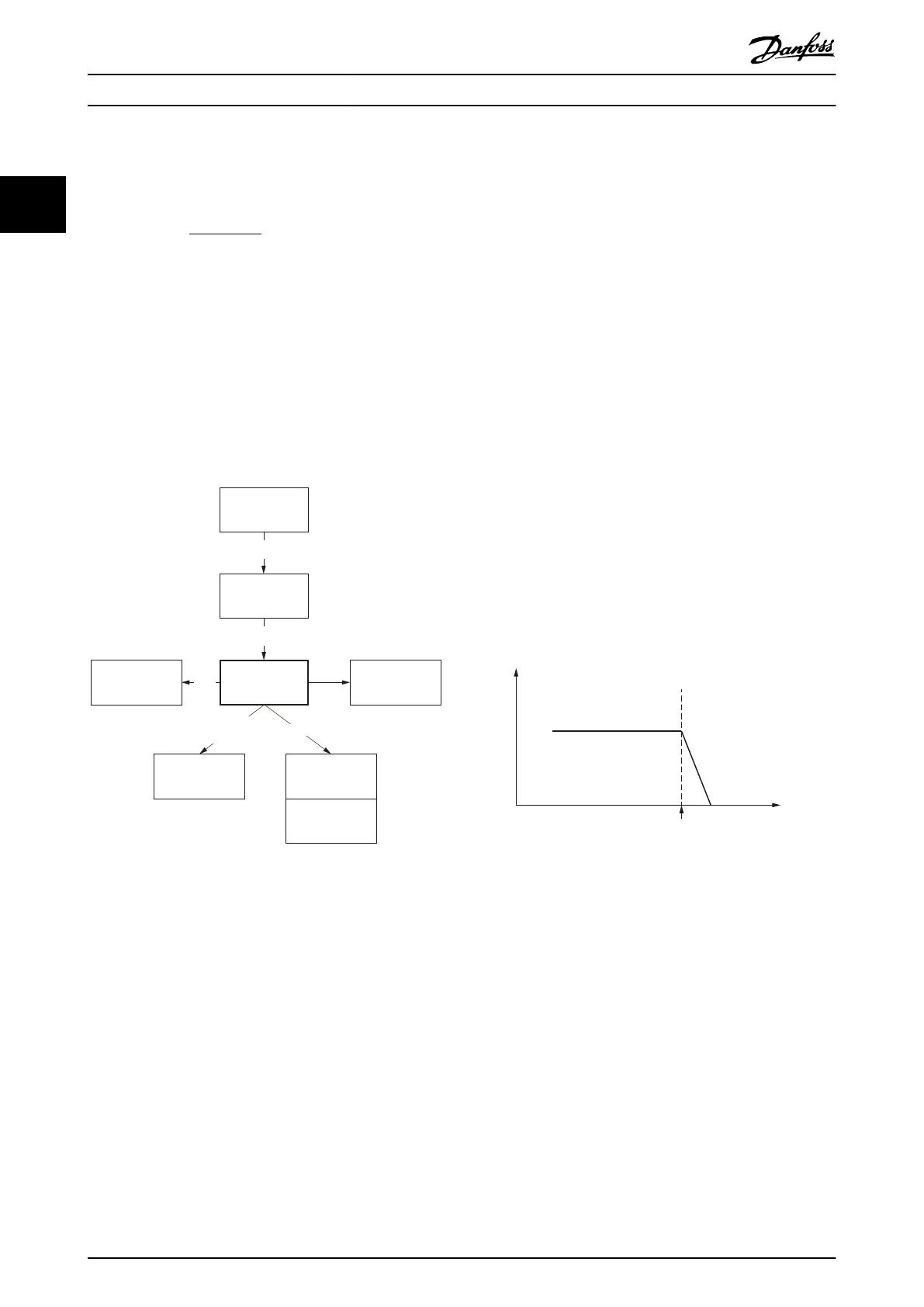
2.3.4 Position Limits
2.3.4.1 Hardware Limit Switch
One method to limit the positions of the servo drive is to
use limit switches (left/negative or right/positive), which
are also referred to as hardware limit switches. The limit
switches must be congured using object 0x200F (see
chapter 7.21.3 Parameter: Dual Analog User Inputs Congu-
ration (0x200F)). When the servo drive reaches the Left
(Right) Limit switch, it ramps down to standstill using the
value set in object 0x6085 (see chapter 7.5.9 Parameter
50-13: Quick Stop Deceleration (0x6085)). It is possible to
command the servo drive out of the limit switch in the
opposite direction. The states of the limit switches are
indicated in object 0x2006 (see chapter 7.22.12 Parameter
50-08: Motion and Input Status (0x2006)).
The servo drive remains in state Operation enabled. If a
motion command is issued that would direct the servo
drive further in the wrong direction, the command is
rejected by setting the command error bit in the
Statusword. The monitoring of the limit switch is edge-
triggered because the signal does not need to remain high
for the duration of the servo drive ramp-down time.
The hardware limit switch is monitored in all modes of
operation.
Position
Hardware
limit switch
Velocity
Quick-stop
deceleration
130BF159.10
Illustration 2.3 Hardware Limit Switch
2.3.4.2 Software Position Limit
The valid positions of the servo drive can also be limited
using software position limits (object 0x607D: Software
position limit). This object indicates the congured
maximum and minimum software position limits and is
used to monitor the position limits in all available modes
of operation.
Supervision of software position limits requires a dened
home position (the Is homed bit in the Statusword must be
set).
The behavior of the servo drive in a position-controlled
mode of operation diers to other modes. In a position-
controlled mode of operation, the drive does not pass over
the software position limit. The target position is limited to
Servo Drive Operation
VLT
®
Integrated Servo Drive ISD
®
510 System
22 Danfoss A/S © 01/2017 All rights reserved. MG36D102
22

 Loading...


