3. Mode
35941
3/5
35941
Self-diagnostic
If the number of PCB in which an error occurred is more than one (1)
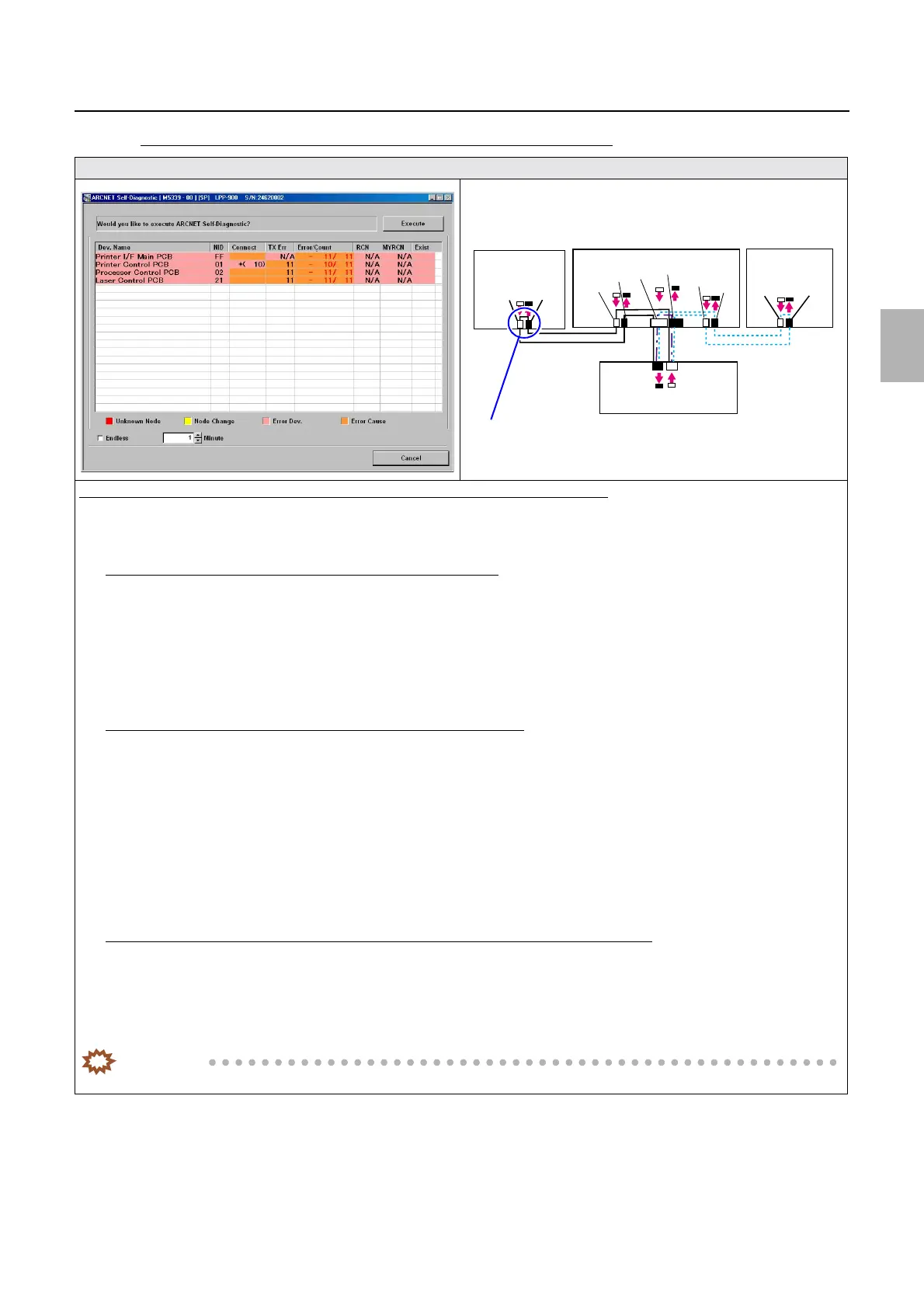
Display
Diagnosis example (when the number of PCB in which an error occurred is more than one (1))
1. Disconnect two cables that are connecting between the processor control PCB and the printer control PCB.
2. Perform ARCNET Self-Diagnostic again.
If an error only occurs in the processor control PCB but not in others
1. It can be assumed that the cause lies in the connection status of the cables between the processor control PCB and the printer
control PCB.
2. Confirm the connection status of cables connecting the printer control PCB to the processor control PCB. ☞68100
3. Confirm the connection status of the connector between the printer control PCB and the processor control PCB, then, if no
problem is found, replace the processor control PCB.
If an error occurs not only in the processor control PCB but also in others
1. Disconnect two cables that are connecting between the printer control PCB and the laser control PCB.
2. Perform ARCNET Self-Diagnostic again.
3. If an error occurs only in the printer control PCB and the laser control PCB, it can be assumed that the cause lies in the
connection status of the cables between the printer control PCB and the laser control PCB.
4. Confirm the connection status of the connector between the printer control PCB and the laser control PCB, then, if no
problem is found, replace the laser control PCB.
☞68100
If an error occurs not only in the
processor control PCB or laser control PCB but also in others
1. It can be assumed that the cause lies in the connection status of the cables between the printer control PCB and the Printer I/F
Main PCB.
2. Confirm the connection status of the connector between the printer control PCB and the Printer I/F Main PCB, then, if no
problem is found, replace the printer control PCB or the Printer I/F Main PCB.
IMPORTANT
• For details about ARCNET cable cutting and cleaning of inside the ARCNET connector, see ☞68100.
J/P224
J/P223
ARCNET
ARCNET
J/P518
J/P517
J/P1517
J/P1516
J/P219
J/P220
J/P222
J/P221
Processor
control PCB
Printer control PCB
Laser control
PCB
Printer I/F main PCB
J/P1208
J/P1207
Disconnect two cables that are connecting Processor control PCB ⇔
Printer control PCB
Distributed by: minilablaser.com