2/5
3. Mode
35941
35941
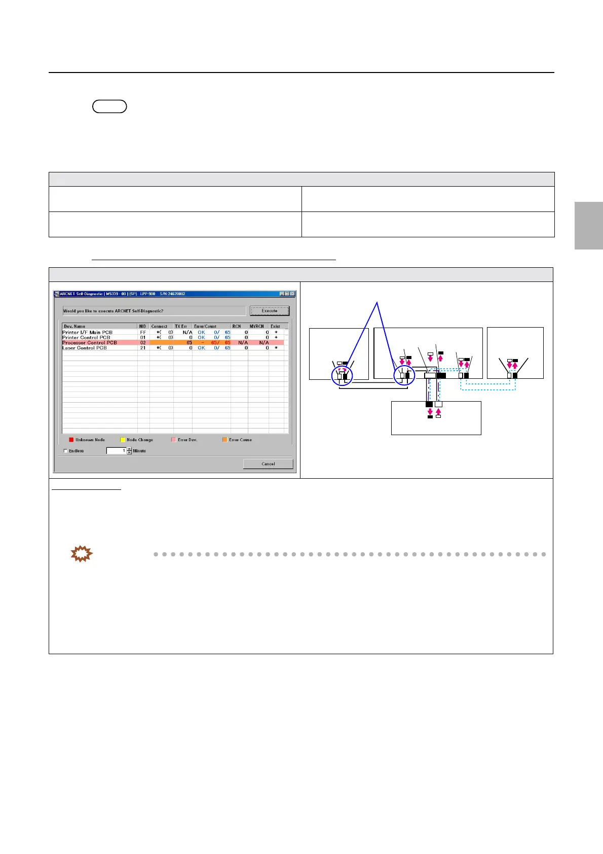
Self-diagnostic
2. Click Execute on the ARCNET Self-Diagnostic display.
NOTE
• Set Minute to the default value of 1 on the ARCNET Self-Diagnostic program then click Execute to confirm the system's
communication status.
3. The ARCNET Self-Diagnostic program diagnoses failed part then shows the result.
Confirm the displayed message and the ARCNET Self-Diagnostic display to diagnose the following.
If the number of PCB in which an error occurred is one
Diagnosis
☞If the number of PCB in which an error occurred is one ☞If the number of PCB in which an error occurred is more than
one (1)
☞If the number of PCB in which an error occurred is more than
one (2)
☞Narrowing down the failure location if the failure location
cannot be determined
Display
Diagnosis example
1. It can be assumed that the cause of the error lies between the PCB in which an error has occurred (Processor control PCB) and the
PCB that transmits signal to that PCB (Printer control PCB).
2. Confirm the state of connection of cables connecting the printer control PCB to the processor control PCB.
IMPORTANT
• Confirm ARCNET cable connection, cable cutting and cleaning of inside the connector on both the printer control
PCB and the processor control PCB sides.
• For details about ARCNET cable cutting and cleaning of inside the ARCNET connector, see
☞68100.
3. Perform ARCNET Self-Diagnostic again.
4. Confirm the connection status of the connector between the printer control PCB and the processor control PCB, then, if no
problem is found, replace the processor control PCB.
J/P224
J/P223
ARCNET
ARCNET
J/P518
J/P517
J/P1517
J/P1516
J/P219
J/P220
J/P222
J/P221
Processor
control PCB
Printer control PCB
Laser control
PCB
Printer I/F main PCB
J/P1208
J/P1207
Cables connecting Processor control PCB ⇔ Printer control PCB
Confirm the connections.
Distributed by: minilablaser.com