3. Mode
35951
2/3
35951
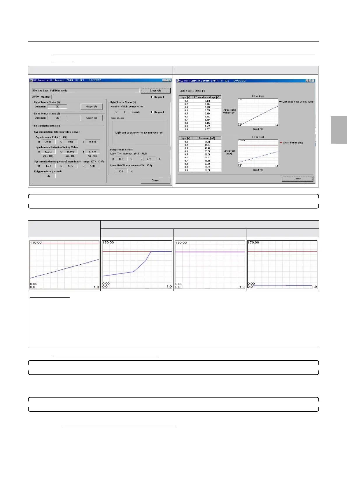
Self-diagnostic
Example: If the diagnosis result is normal (FRONTIER-Printer: Ver. 3.0 or later, QSS-Printer: Ver. 5.0
or later)
4. Right Source Status (R) and Right Source Status (B) are abnormal
Confirm graph (R) and graph (B).
Diagnosis example (when problem lies in G laser)
5. Synchronous Detection Setting Value G is abnormal
• Confirm that there is no connection failure in wiring between the laser control PCB and the laser unit.
• Confirm that there is no connection failure in wiring between the laser control PCB and the G-AOM driver.
6. Perform Laser Self-Diagnostic (AUTO) again, and if it still recurs, replace the G-AOM driver.
1. Perform Laser Self-Diagnostic (AUTO) again.
Synchronous Detection Setting Value
G is abnormal
• There is a possibility of failure in the laser unit.
1. Countermeasure 1: reattach the G-AOM driver then replace the laser unit.
2. Countermeasure 2: diagnose again by Laser Self-Diagnostic (AUTO) .
Laser Self-Diagnostic Laser Self-Diagnostic (graph (R))
LD current graph (normal) LD current graph (abnormal)
Graph (1) Graph (2) Graph (3)
Diagnosis example
• ☞Graph (1), ☞Graph (2)
If the graph of the LD current is not showing a straight line but a polygonal line that touches the upper bound or keeps touching it, it
is assumed that the laser unit LD is deteriorated.
Countermeasure: replace the laser unit.
•
☞Graph (3)
If the graph of the LD current is showing a horizontal line that lies near 0 mV level, connection failure in the laser control PCB
connector (coaxial cable (R)) or failure in the laser control PCB can be suspected.
Distributed by: minilablaser.com