3. Mode
36060
3/3
36060
Printer Mechanical Adjustment
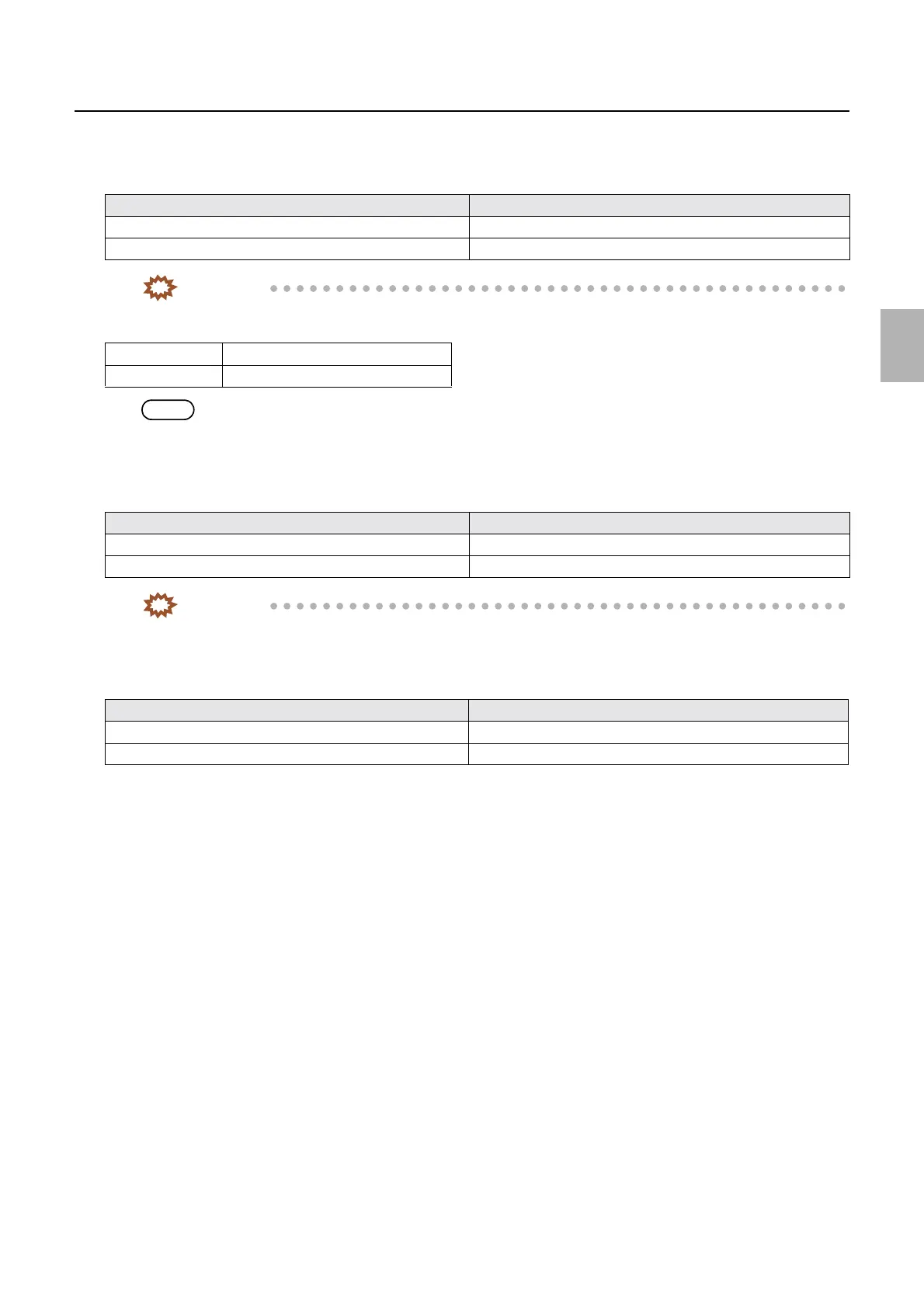
9. After the correction, make test prints in Test Print (Confirmation) of Functions. And then check that
the difference of dimensions of lines A and C (on the second test print) is within the allowable range in
the following table.
IMPORTANT
• If the difference of dimensions of lines A and C (on the second test print) is out of the tolerance level, input the
correction value to A−C.
NOTE
• When correcting 1.0 mm in (A-C), the zigzagging of approx. 1.0 mm can be corrected on the test print.
10. Make test prints in Test Print (Confirmation) of Functions. And then check that the difference of
dimensions of lines A and C (on the second test print) and the difference of dimensions of lines A and C
(on the first test print) are within the allowable range in the following table.
IMPORTANT
• If the difference between lines A and C is not within the allowable range, check the zigzagging adjustment of
the magazine mount.
☞22100
• If the differences of lines A and C both on the first and second test prints are out of the allowable range
specified in the following table, confirm the exposure center correction.
☞36070
Test print Tolerance range
Test print 1 (457.0 mm) A − C is within ±0.5 mm
Test print 2 (914.0 mm) A − C is within ±1.0 mm
A is longer than C Positive correction
C is longer than A Negative correction
Test print Tolerance range
Test print 1 (457.0 mm) A − C is within ±0.5 mm
Test print 2 (914.0 mm) A − C is within ±1.0 mm
Test print Tolerance range
Test print 1 (457.0 mm) A and C are within 1/2±0.5 mm of the actual paper width
Test print 2 (914.0 mm) A and C are within 1/2±1.0 mm of the actual paper width
Distributed by: minilablaser.com