4/4
6. Electrical parts
63280
63280
Positions of electrical parts (Processor section)
*1. For details about processor section fan operation specification, see ☞63321.
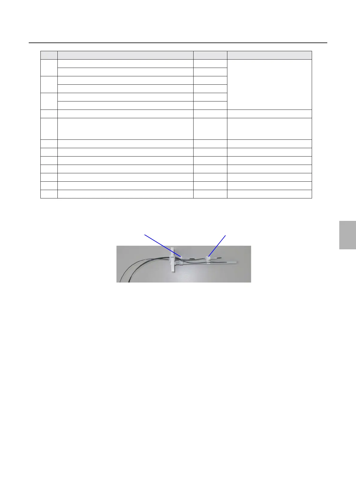
*2. For details about # # # replenishment solution level sensors, see the following image.
For replacing the replenishment solution level sensor, see
☞27530.
*3. After replacing each electrical part, see Processor section (List of adjustment after electrical parts replacement)
☞63312.
17 P1R (Upper) Replenishment Solution Level Sensor SE63
*2*3
P1R (Lower) Replenishment Solution Level Sensor SE64
18 P2RA (Upper) Replenishment Solution Level Sensor SE65
P2RA (Lower) Replenishment Solution Level Sensor SE66
19 P2RB (Upper) Replenishment Solution Level Sensor SE67
P2RB (Lower) Replenishment Solution Level Sensor SE68
20 Temperature and humidity sensor SE69
21 Drive motor M11 If replaced, perform Drive Motor
Revolution Count Setting.
☞33502
22 Exhaust fan FAN13 Exhaust
*1
23 Drive motor cooling fan FAN16 Blowing
*1
24 Tank cooling fan 3 FAN12 Exhaust
*1
25 Tank cooling fan 2 FAN11 Exhaust
*1
26 CD effluent float switch FS7
27 STB effluent float switch FS9
28 Rack stopper sensor LS14
No. Name Symbol Remarks
# # #(Lower) replenishment solution level sensor
# # #(Upper) replenishment solution level sensor
G085370
Distributed by: minilablaser.com