6. Electrical parts
63310
2/4
63310
Positions of electrical parts (Processor section)
2 BF processing solution float switch FS2
BF refilling water level
BF processing solution level
BF safety thermostat
3 STB1 processing solution float switch FS3
STB1 refilling water level
4 STB4 processing solution float switch FS6
STB4 refilling water level
STB4 processing solution level
STB4 safety thermostat
5 CD effluent float switch FS7
6 BF effluent float switch FS8 Option
7 STB effluent float switch FS9
8 SW/DW Tank Level Sensor LSE3
9 SW Tank Level Sensor LSE4
10 CD thermosensor TH1
11 BF thermosensor TH2
12 STB thermosensor TH3
13 Interlock switch (Processor top cover) LS4
14 Rack stopper sensor LS14
15 Power supply cooling fan 1 FAN14 Circulation
*1
16 Exhaust fan FAN13 Exhaust
*1
17 Drive motor cooling fan FAN16 Blowing
*1
18 Tank cooling fan 1 FAN10 Intake
*1
19 Tank cooling fan 3 FAN12 Exhaust
*1
20 Tank cooling fan 2 FAN11 Exhaust
*1
21 Drive motor M3 If replaced, perform Drive Motor
Revolution Count Setting.
☞33502
22 CD circulation pump P1
23 BF circulation pump P3
24 STB1 circulation pump P5
25 STB2 circulation pump P6
26 STB3 circulation pump P7
27 STB4 circulation pump P8
28 Cleaning pump 1 P15
29 CD water supply pump RP1
30 BF water supply pump RP2
31 STB water supply pump RP3
32 CD heater H1
33 BF heater H2
34 STB heater H3
35 Hour meter HM1 Option
36 CD digital flowmeter FLS1 Option
37 STB tablet conveyor motor DM5
38 Earth leakage circuit breaker 1 NFB2 See
☞4203.
39 Earth leakage circuit breaker 2 NFB3
40 Earth leakage circuit breaker 3 NFB4
41 Power supply cooling fan 2 FAN18 Exhaust
*1
42 Terminal strip 1 TA1
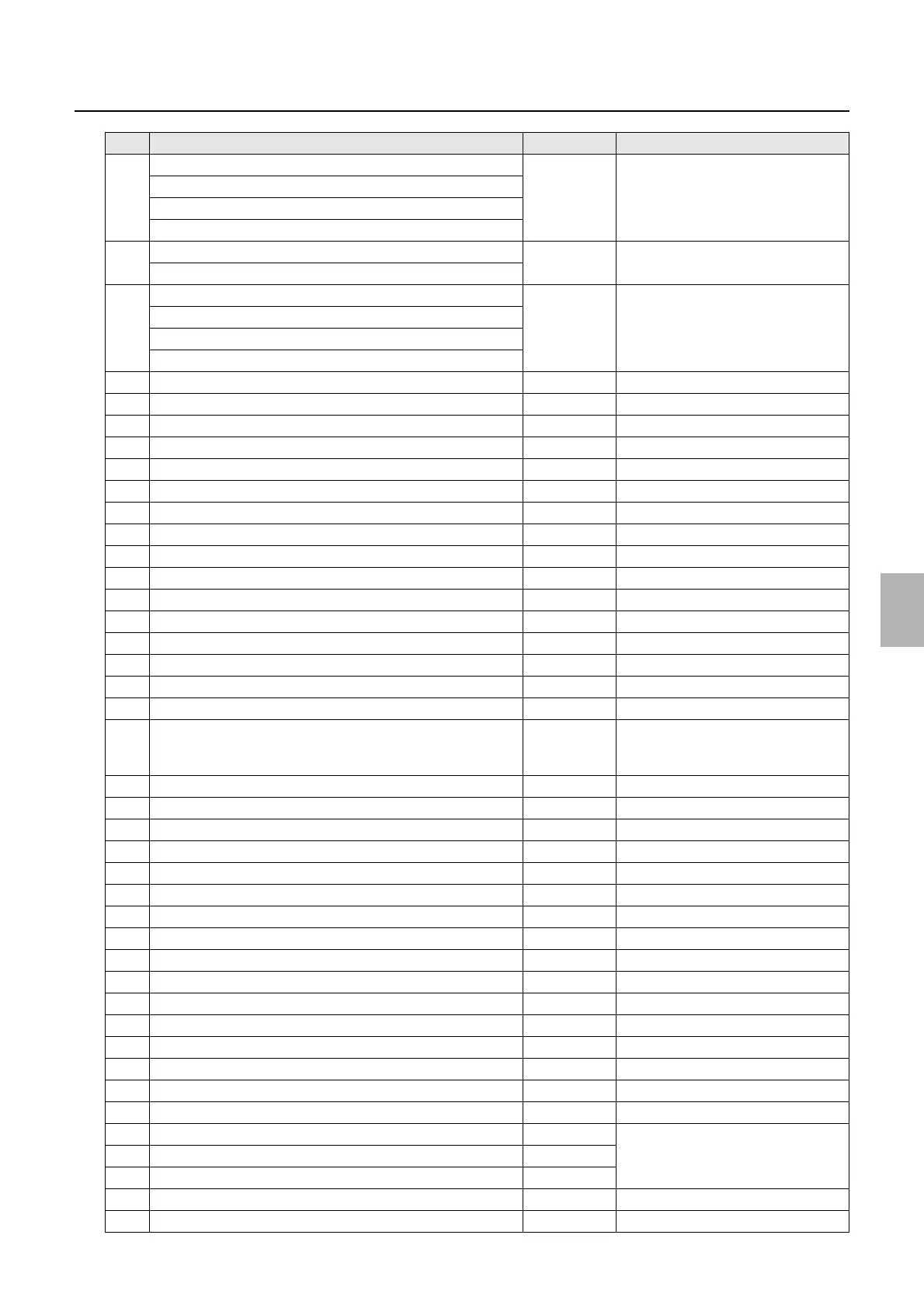
No. Name Symbol Remarks
Distributed by: minilablaser.com



 To Next Page