Description of PCB (printer section)
1/1
6. Electrical parts
66008
66008
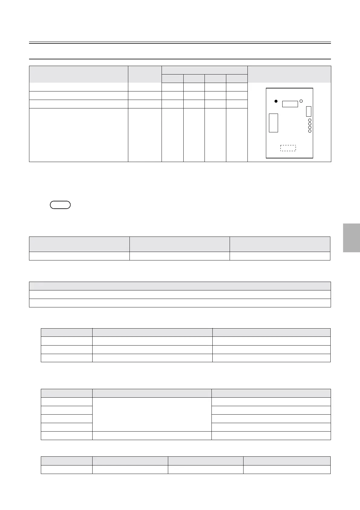
Capacity booster PCB
*1. The status of capacity booster PCBs F, G, H and I shows.
!
!!
! Function
• The processing capacity of the system can be changed by installing capacity booster PCB and Capacity Booster Software.
NOTE
• The Capacity Booster Software and capacity booster PCB cannot be ordered separately.
!
!!
! Reference
!
!!
! Adjustments and precautions for PCB replacement
!
!!
! Unused connector
•
!
!!
! Component parts table
*1. When the capacity booster PCB F is normally detected
Name Part No. Status from LED1 to LED4
*1
Illustration
LED1 LED2 LED3 LED4
Capacity booster PCB F J391452 Off On Off Off
Capacity booster PCB G J391453 On On Off Off
Capacity booster PCB H J391454 Off Off On Off
Capacity booster PCB I J391455 On Off On Off
Layout diagram Symptom due to the poor connection of
wiring
Symptoms of fuse blowout
☞63000 ☞4202 -
Explanation
• Install Capacity Booster Software.
• After installing the Capacity Booster Software, click OK on the Machine Specification display.
Connector No. Purpose Remarks
P861 Used for connecting to other capacity booster PCB Used only for capacity booster PCB F
P862 Used for connecting to other capacity booster PCB Used only for capacity booster PCB G
CN1 Unused
LED No. Purpose Status
LED1 For checking the detection status of the capacity
booster
OFF
*1
LED2 On when the power supply is turned on.
*1
LED3 OFF
*1
LED4 OFF
*1
LED5 DC+5 V input check On when the power supply is turned on.
Test point No. Purpose Measurement with voltmeter Remarks
TP1 Ground Possible Not mounted
J861
J862
J860
CN1
LED4
LED3
LED2
LED1
LED5
TP1
J39145#
Booster
Distributed by: minilablaser.com