CHAPTER 4: INTERFACES, SETTINGS & ACTUAL VALUES 4.1 ENERVISTA 650 SETUP SOFTWARE
GEK-106310-AF F650 DIGITAL BAY CONTROLLER 4-25
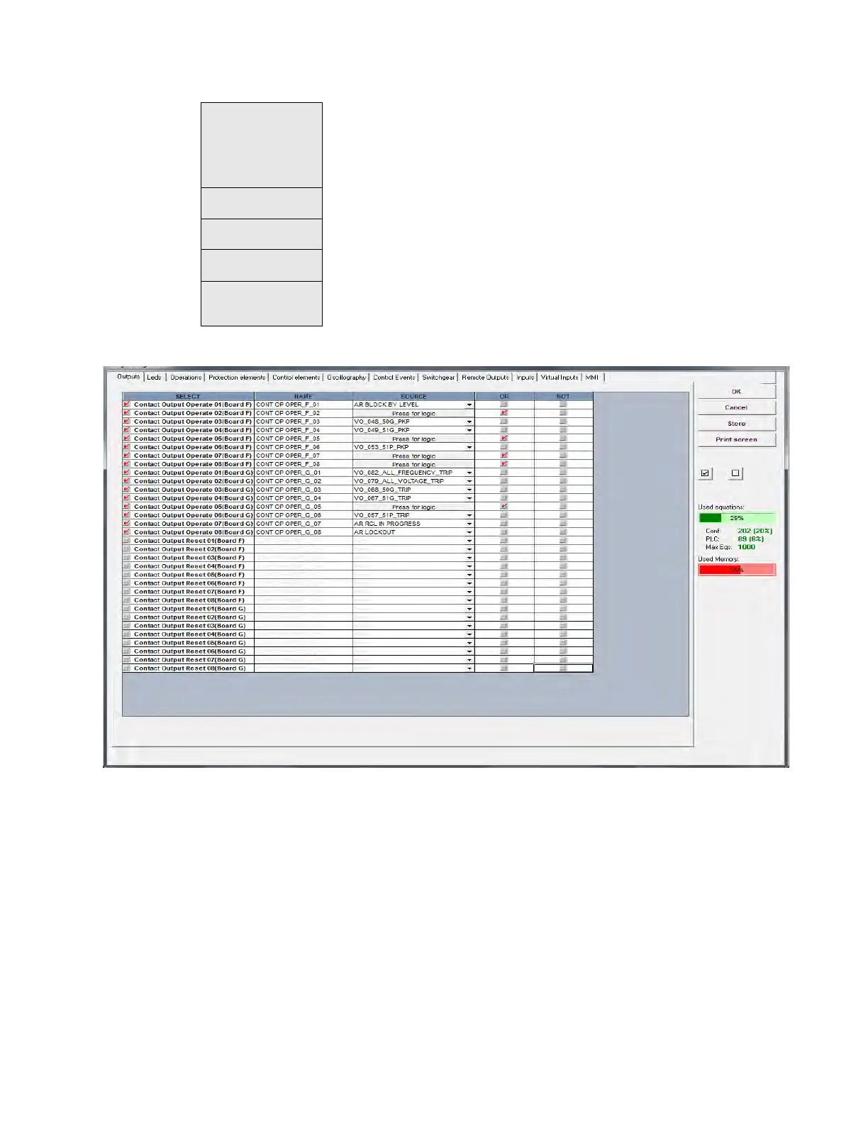
The following figures show an example of the default factory configuration for F650:
Figure 4-11: Relay configuration
Switchgear Up to 16 configurable switchgear elements. A switchgear element can be a breaker, a line
selector switch, a grounding selector switch, a busbar selector switch, etc. This screen
allows configuration of type of contacts, opening and closing time, contact assignation
and text for events related to switchgear. There are 64 pre-established events for
switchgear, which correspond to opening, closing, Error01 and Error11 of the 16
programmable switchgear elements.
Remote outputs Up to 32 DNA bits and 64 user St bits to be transmitted to remote devices over CAN using
GSSE messages
Inputs Text configuration for offline mode file management for all the contact inputs available in
device.
Virtual Inputs Text configuration for offline mode file management. 32 latched and 32 self reset virtual
inputs.
MMI (HMI-Human
Machine Interface)
Screen one line diagram configuration. This menu shows a canvas to draw a simplified
one-line diagram of a bay in a feeder, line, transformer, etc. The menu includes a library for
power elements, metering elements, text and drawings. See an example on the next page.