4-24 F650 DIGITAL BAY CONTROLLER GEK-106310-AF
4.1 ENERVISTA 650 SETUP SOFTWARE CHAPTER 4: INTERFACES, SETTINGS & ACTUAL VALUES
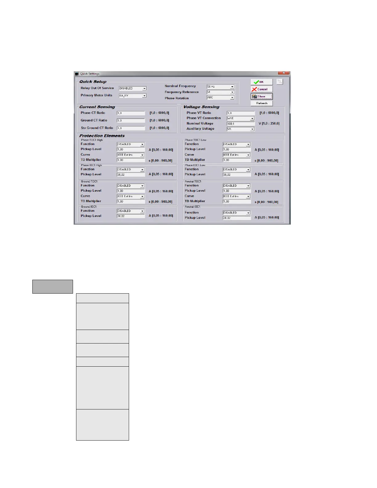
4.1.7.8 Quick settings menu
This menu allows quick access to the main Setpoints of the relay.
Figure 4-10: Quick Settings
4.1.7.9 Relay configuration menu
This is the relay configuration section in which the relay can be configured using internal states or already compiled
equation on PLC Editor
.
Relay
Configuration
Outputs Configuration of contact output operate and reset signals for all boards.
LEDs
15 LEDs fully configurable from any logical variable, contact or virtual input. First 5
LEDs
are latched by hardware, the rest are self-reset but can be latched through PLC
configuration. For firmware version 7.20 and higher, all 15 LEDs can be latched by setting.
From the LED configuration screen, it is possible to print the vertical LED label for the relay.
Operations Configurable operations up to 24. Operation texts, interlocks, final states, frontal keys, time
outs and masters.
Protection Elements This tab allows assigning operands (logic signals) as inputs to different protection
elements. To block, reset, initiate the different protection elements inputs.
Control Elements This tab allows assigning operands (logic signals) as inputs to different control elements.
Oscillography Trigger and up to 16 digital channels to be included in oscillography records, are
programmable from any logical variable, contact or virtual input. Text configuration is only
for offline mode.
NOTE: T
his screen is used for the configuration of digital channels and oscillography
trigger. The rest of parameters, such as function enabling/disabling, sampling rate,
number of oscillography files, etc. must be set on the Setpoint > Product Setup >
Oscillography menu.
Control Events Up to 128 user programmable events from any logical variable, contact or virtual input.
Possibility to display the event as an alarm on the alarms panel. Control events are also
displayed in the snapshot events recording. 1 ms time tagging.
A control event is a logic signal associated with an operand or combination of operands,
t
hat allows following the status of that signal.