5-132 F650 DIGITAL BAY CONTROLLER GEK-106310-AF
5.5 CONTROL ELEMENTS CHAPTER 5: SETPOINTS
Care must be taken when configuring the delay for an IOC or TOC element that is being supervised by CT Supervision
Failure function. The delay time in the IOC function should be set to a value 10 ms greater than CT Supervision Failure
delay timer
5.5.12 Second harmonic inhibit
For firmware 7.50 or above, the F650 incorporates one Second Harmonic Inhibit element which can be used to block
sensitive elements when particular level of inrush currents is detected in phase currents.
During transformer energization, the inrush current presenting in phase currents may impact some sensitive elements,
such as neutral directional overcurrent. Therefore, the ratio of the second harmonic to the fundamental magnitude per
phase is monitored, while exceeding the settable pickup level, an inhibit signal is asserted, which can be used to block such
sensitive elements. In order to get proper functionality, 2
nd
Harmonic Inhibit delay must be minor than delay of IOC or TOC
element that is being supervised by 2
nd
Harmonic inhibit function.
Second harmonic function settings are available in Enervista 650 setup at Setpoint > Control Elements > 2
nd
HRMC
Inhibit
Function This setting allows enabling and disabling the 2
nd
Harmonic Inhibit function.
2nd HRMC PICKUP This setting sets the Phase Current 2nd Harmonic value required to allow the Second
Harmonic Inhibit element to pick up.
2nd HRMC DELAY This setting specifies the pickup time delay for this function to operate after pickup.
Note that
MINIMUM CURRENT Sets the minimum value of fundamental secondary current required to allow the
Second Harmonic Inhibit element to operate.
If Phase for Operation is set to AVERAGE, the average of three-phase currents is used
for supervision. The similar adaptive average algorithm is applied to calculate the
average of operation current magnitude.
PHASES FOR OPERATION This setting defines the phases required for operation, and the detail is explained
below:
• ANY ONE: At least one phase picked up.
• ANY TWO: Two or more phases picked up.
• ALL THREE: All three phases picked up.
• AVERAGE: The average of three-phase harmonics picked up.
If set to AVERAGE, the relay calculates the average level of the second harmonic and
compares this level against the pickup setting. Averaging of the selected harmonic
follows an adaptive algorithm depending on the fundamental current magnitude per-
phase. Only phases where the fundamental current exceeds the cut-off level are
included in the average.
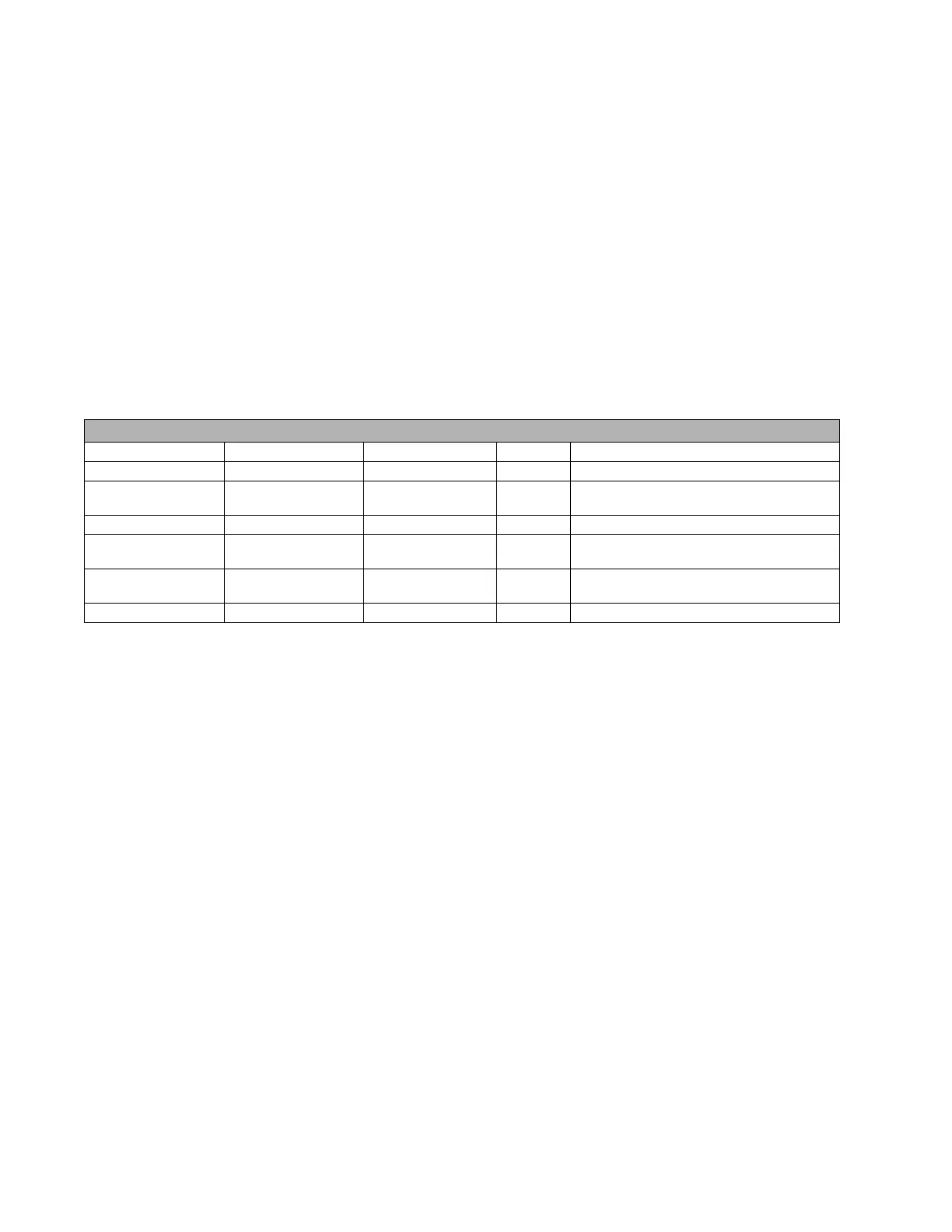
SETPOINTS ð CONTROL ELEMENTS ð 2
nd
HRMC Inhibit
SETTING DESCRIPTION NAME DEFAULT VALUE STEP RANGE
Function Function DISABLED N/A [DISABLED – ENABLED]
Second harmonic
pi
ckup
2ND HRMC PICKUP 1 1% [1- 40.00]
Second harmonic delay 2ND HRMC DELAY 0.00 0.1s [0.00-600.00]
Minimun secondary
c
urrent to operate
MINIMUM. CURRENT 0.05 0.01A [0.05-15.00]
Phase affected to
op
erate
PHASES FOR
OPERATION
ANY ONE N/A [ANY ONE- ANY TWO- ALL THREE- AVERAGE]
Snapshot events Snapshot events DISABLED N/A [DISABLED – ENABLED]