CHAPTER 4: INTERFACES, SETTINGS & ACTUAL VALUES 4.1 ENERVISTA 650 SETUP SOFTWARE
GEK-106310-AF F650 DIGITAL BAY CONTROLLER 4-19
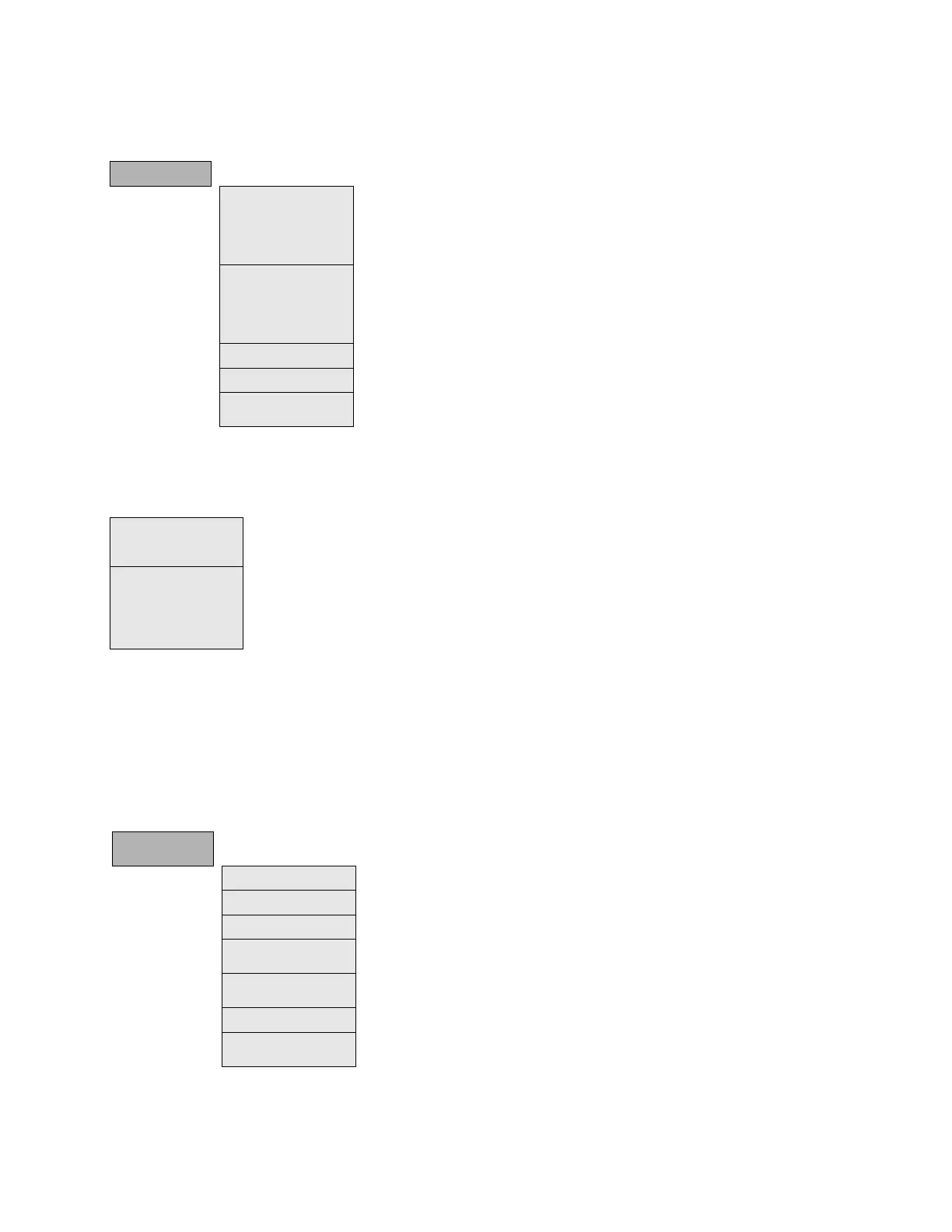
4.1.7.3 System setup menu
(*) indicates online only, (**) indicates offline only
4.1.7.4 Breaker menu
4.1.7.5 Protection elements menu
This option shows all protection elements available in the relay as shown in the following two tables (exact menu depends
on firmware version).
For firmware versions below 7.50, each group of protection elements includes the specific protection units of the same
type. For example phase currents group includes TOC, IOC, directional units, etc. There are three groups available, so there
are three protection units of each function that can work in grouped mode or ungrouped (altogether).
Table 4-4: Protection elements menu, firmware version below 7.50
(*) indicates online only, (**) indicates offline only
SYSTEM SETUP
General Settings This screen describes and enables the settings of the power system where the relay
operates. Some of these settings are used only for metering values presentation purposes;
however, some of them apply directly to the sampling and analog-digital conversion
process (rated frequency setting). Therefore, these settings need to be adjusted to fit the
system settings.
Flex Curves Flex Curves – Programmable user curves: The relay incorporates 4 user curves called Flex
Curve A, B, C and D. The points for these curves are defined by the user in Setpoint >
System Setup > Flex Curves > Edit Curve menu in EnerVista 650 Setup. User defined flex
curves can be selected as an operation curve in all the time overcurrent functions in the
relay.
Breaker Breaker Configuration
Switchgear: Configuration of snapshot events for each switchgear (enable or disable)
Miscellaneous Settings This screen contains settings related with relay working mode. Out of service setting,
Local/Remote mode and Active language mode are options listed below.
Breaker settings Breaker settings, maintenance and switchgear selection of the device configured as breaker in the F650. The
selected switchgear is used in recloser, breaker failure and synchronism functions. The settings are Number of
Switchgear, Maximum KI2t, KI2t Integ. Time, Maximum Openings, Max.Openings 1 hour and Snapshot Events.
Breaker maintenance
These settings correspond to the initialization of (KI)
2
t counters, and the counting of number of openings and
closings of the switchgear configured as breaker. These Counters allow the breaker Maintenance. They are
used to cumulate the breaker ageing produced by a trip or a breaker opening. In order to incorporate the
breaker historic, in case of existing breakers, the system allows assigning an initial value to accumulated
amperes, and to the number of opening and closing operations.
Protection
Elements
Phase Current All overcurrent functions for phase current.
Neutral Current All overcurrent functions for neutral current. (Calculated from phases, not measured)
Ground Current All overcurrent functions for ground current. (Measured from 4th current input)
Sensitive Ground
Current
All overcurrent functions for sensitive ground current. (Measured from 5th current input)
Negative Sequence
Current
All Negative sequence overcurrent functions.
Voltage Elements All voltage functions for phases, neutral, ground and auxiliary voltage
Power Forward power, directional power and wattmetric ground fault (High and Low) protection
functions.