7-192 F650 DIGITAL BAY CONTROLLER GEK-106310-AF
7.2 IEC 61850 PROFILE FOR F650 CHAPTER 7: IEC 61850 PROTOCOL
7.2.7.3.11 PIXIT for 650 family of relays whose order code has Rear Ethernet Communication Board 2
option "H", "G", "K", "J", "L", "M" and IEC 61850 Edition 2
Reference documentation: PIXIT for 650 family of relays v1_6 firm7_20.
This document describes the:
• PIXIT for Association Model
• PIXIT for Server model
• PIXIT for Dataset model
• PIXIT for Reporting model
• PIXIT for Generic substation events model
• PIXIT for Control model
• PIXIT for Time and time synchronisation model
• PIXIT for File transfer model
This document specifies the protocol implementation extra information for testing (PIXIT) of the IEC 61850 interface in 650
family of relays.
Together with the PICS and the MICS the PIXIT forms the basis for a conformance test according to IEC 61850-10.
Contents of this document: Each chapter specifies the PIXIT for each applicable ACSI service model as structured in IEC
61850-10.
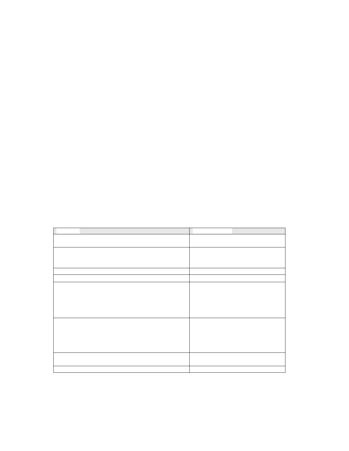
1 Pixit For Association Model
Description Value / Clarification
Maximum number of clients that can set-up an association
simultaneously
5
TCP_KEEPALIVE value. The recommended range is 1..20s
5 seconds but if no application message is
detected within the As3 value, the device
closes the connection.
Lost connection detection time
120 seconds (Configurable)
Authentication is not supported yet
What association parameters are necessary for successful
association
Transport selector Y
Session selector Y
Presentation selector Y
AP Title N
AE Qualifier N
If association parameters are necessary for association, describe
the correct values e.g.
Transport selector 0001
Session selector 0001
Presentation selector 00000001
AP Title NA
AE Qualifier NA
What is the maximum and minimum MMS PDU size Max MMS PDU size 120000
Min MMS PDU size32000.
What is the maximum start up time after a power supply interrupt 90 seconds