CHAPTER 4: INTERFACES, SETTINGS & ACTUAL VALUES 4.2 HUMAN-MACHINE INTERFACE (HMI)
GEK-106310-AF F650 DIGITAL BAY CONTROLLER 4-47
4.2.6.6 View settings menu
To enter this menu press the enter/shuttle key when the option View Settings is selected in main menu (o). A secondary
level is displayed with different sublevels. Pressing up-down keys or rotating the shuttle key, (left for moving up and right
for moving down) select the next level to be displayed (o), press the enter/shuttle key again to enter in next level and press
esc key to return to previous level if desired. This navigation is performed the same for all the menus in "View Settings".
Once the last sublevel is reached, move up and down to see the available settings.
AB phase A to phase B
BC phase B to phase C
CA phase C to phase A
3PHASE Three-phase faults (shown on the display as 3PH)
NAF
Fault type not calculated
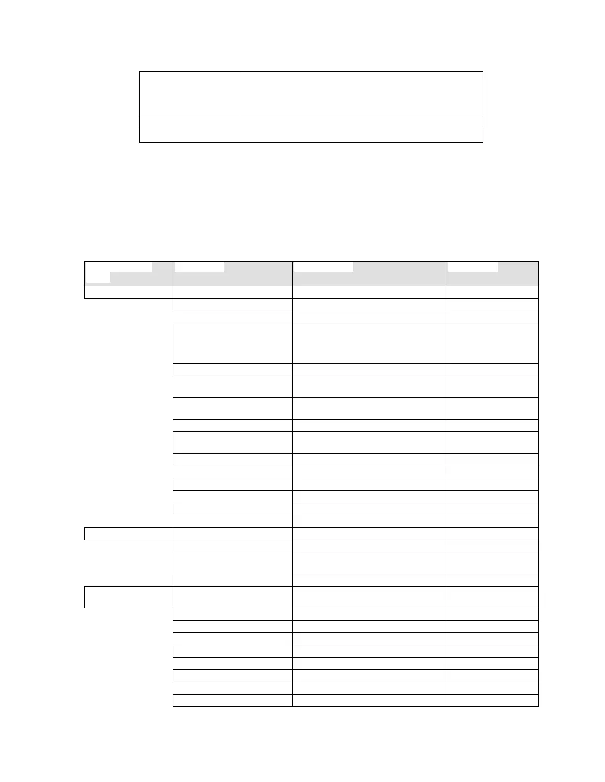
MAIN SETTINGS
MENU
FIRST LEVEL SECOND LEVEL THIRD LEVEL
Product Setup >
Communication >
Serial Ports
Ethernet > Ethernet A
Ethernet B
Ethernet E
Redundancy
ModBus Protocol
DNP3 Slave (Available for standard and
IEC6
1850 models)>
DNP3 Slave 1..3
IEC 870-5-104(Available for standard and
IEC6
1850 models)>
SNTP
PROCOME (Available for procome models
only).
PTP 1588
Routing
Fault Report
Oscillography
Demand
Time Settings
System Setup >
General Settings
Breaker > Breaker Settings
Breaker Maintenance
Misc. settings
Protection Element >
(*) See note
Phase Current >
Phase TOC High > Phase TOC High 1..3
Phase TOC Low > Phase TOC Low 1..3
Phase IOC High > Phase IOC High 1..3
Phase IOC Low > Phase IOC Low 1..3
Phase Directional > Phase Directional 1..3
Thermal Model > Thermal Model 1..3
Neutral Current >