5-28 F650 DIGITAL BAY CONTROLLER GEK-106310-AF
5.2 PRODUCT SETUP CHAPTER 5: SETPOINTS
Being Y the power considered in each case.
W Three-phase active power
VAR Three-phase reactive power
VA Three-phase apparent power
The maximum demanded value is stored in non-volatile memory. It is not cleared when the relay is turned off. When the
relay is turned on again, the maximum values are updated.
States associated with the demand (“Actual>Status>Records Status>Demand”) are the following:
Table 5-12: Demand associated values
Besides the previously considered demand measures, two states are used for demand control:
DEMAND TRIGGER INP Bit type state, Programmable at “Setpoint>Relay Configuration>Protection Elements” in the
EnerVista 650 Setup software. This signal is used by the Block Interval demand method.
DEMAND RESET INP Bit type state, programmable at “Setpoint>Relay Configuration>Protection Elements” in the
EnerVista 650 Setup software. When this bit is activated, the demand measures are reset. All
stored values are reset to zero (for demand dates, this value represents January 1
st
, 2000).
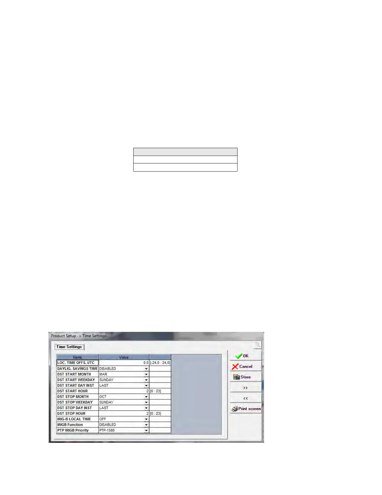
5.2.7 Time Settings
The date and time can be synchronized to a known time using the SNTP protocol, IRIG-B protocol (when it provides UTC
Time) or IEEE1588 (Available starting from version V7.00) and the TIME SETTINGS allow setting the date and time provided
by these protocols to the proper local time on the Real Time Clock.
When there is no SNTP protocol enabled, IRIG-B protocol is not set to UTC Time or IEEE1588 synchronization, the TIME
SETTINGS are not used in the Real Time Clock but are still used to calculate the UTC Time (i.e., for the IEC61850 protocol),
but its behavior is not assumed correct in several critical hour changes because of Daylight Savings Time getting effective.
In these configuration cases, it is recommended to disable Daylight Savings Time.
Table 5-13: Time Settings
DEMAND ASOCIATED STATES
DEMAND TRIGGER INP
DEMAND RESET INP