5-176 F650 DIGITAL BAY CONTROLLER GEK-106310-AF
5.10 LOGIC CONFIGURATION (PLC EDITOR) CHAPTER 5: SETPOINTS
5.10.1 Theory of operation
5.10.1.1 Description
As already mentioned in the introduction, this tool uses FBD mode of IEC 61131-3 standard. For this purpose we have
defined a series of basic operations with illustrations below.
The basic operations available in the PLC Editor are located in the tool bar of the application and are as follows:
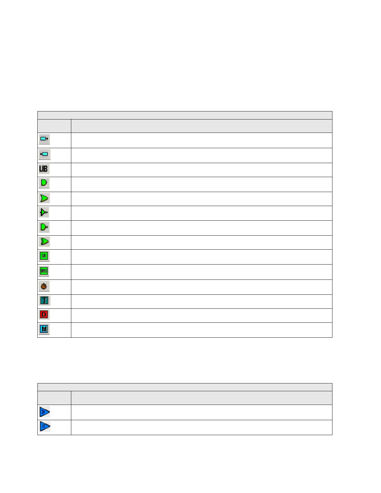
Table 5-97: PLC editor basic operation in F650
For firmware 7.20 or above, analog operands are available. It is possible to use these operands with analog or digital
values.
The basic operations available in PLC Editor are located in the tool bar of the application and are as follows:
PLC EDITOR BASIC OPERATION
ICONS IN
SCREEN
DESCRIPTION
INPUT TO LOGIC: Selection of the digital input to the logic. (All available internal status can be used as logic inputs **)
OUTPUT FROM LOGIC: Virtual output built with internal logic. (Up to 512)
LIBRARY: Possibility to build blocks of logic in a simple graphic object. OR and AND from 3 to 8 inputs are provided as
li
braries.
AND of two digital inputs.
OR of two digital inputs.
NOT of a digital input.
NAND of two digital inputs.
XOR of two digital inputs.
SR: Latch (set-reset): reset dominant.
ONS: signal to pulse an logic input to a signal of one scan cycle length.
TIMER: timer signal with set, reset and mask for timing.
TEXT LABEL: text to customize the logic configuration file.
Flip-Flop D: signal that maintains the actual value frozen during a PLC cycle
MASK: Time mask to be used in timing operations.
PLC EDITOR ANALOG OPERATION
ICONS IN
SCREEN
DESCRIPTION
GREATER THAN COMPARATOR of two digital or analog inputs.
EQUAL TO COMPARATOR of two digital or analog inputs