CHAPTER 5: SETPOINTS 5.4 PROTECTION ELEMENTS
GEK-106310-AF F650 DIGITAL BAY CONTROLLER 5-51
5.4.2.3 IAC curves
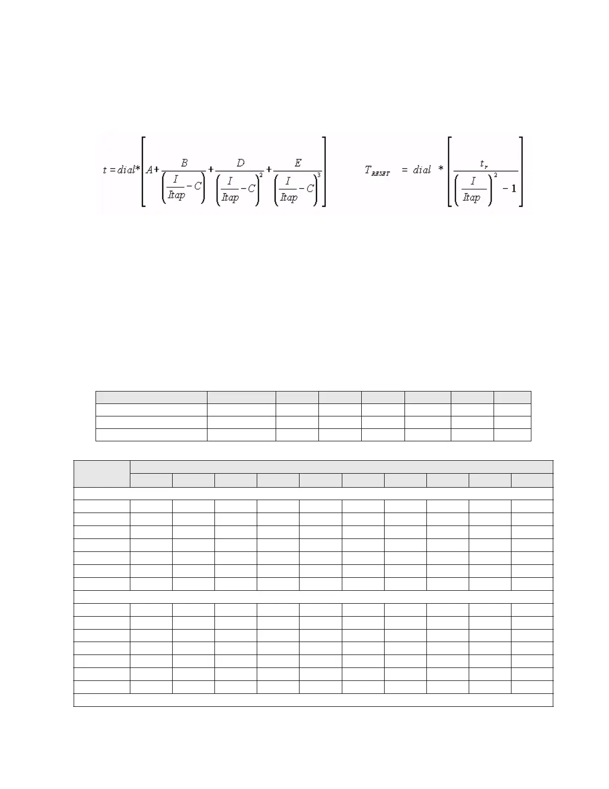
This family of curves follows the time response of the General Electric IAC electromechanical relays. The following formulas
define these curves:
Where:
t = Operation time in seconds
Dial = multiplier setting
I = Input current
Itap = Current pickup value
A, B, C, D, E = predefined constants
T
RESET
= reset time in seconds
t
r
= characteristic constant.
Table 5-25: Constants for IAC curves
Table 5-26: Tripping time in seconds for IAC curves
IAC Curve Shape Name A B C D E tr
IAC Extremely Inverse IAC Ext Inv 0.0040 0.6379 0.6200 1.7872 0.2461 6.008
IAC Very Inverse IAC Very Inv 0.0900 0.7955 0.1000 -1.2885 7.9586 4.678
IAC Inverse IAC Mod Inv 0.2078 0.8630 0.8000 -0.4180 0.1947 0.990
Dial Current (I/Itap)
1.5 2.0 3.0 4.0 5.0 6.0 7.0 8.0 9.0 10.0
IAC Extremely Inverse
0.5 1.699 0.749 0.303 0.178 0.123 0.093 0.074 0.062 0.053 0.046
1.0 3.398 1.498 0.606 0.356 0.246 0.186 0.149 0.124 0.106 0.093
2.0 6.796 2.997 1.212 0.711 0.491 0.372 0.298 0.248 0.212 0.185
4.0 13.591 5.993 2.423 1.422 0.983 0.744 0.595 0.495 0.424 0.370
6.0 20.387 8.990 3.635 2.133 1.474 1.115 0.893 0.743 0.636 0.556
8.0 27.183 11.987 4.846 2.844 1.966 1.487 1.191 0.991 0.848 0.741
10.0 33.979 14.983 6.058 3.555 2.457 1.859 1.488 1.239 1.060 0.926
IAC Very Inverse
0.5 1.451 0.656 0.269 0.172 0.133 0.113 0.101 0.093 0.087 0.083
1.0 2.901 1.312 0.537 0.343 0.266 0.227 0.202 0.186 0.174 0.165
2.0 5.802 2.624 1.075 0.687 0.533 0.453 0.405 0.372 0.349 0.331
4.0 11.605 5.248 2.150 1.374 1.065 0.906 0.810 0.745 0.698 0.662
6.0 17.407 7.872 3.225 2.061 1.598 1.359 1.215 1.117 1.046
0.992
8.0 23.209 10.497 4.299 2.747 2.131 1.813 1.620 1.490 1.395 1.323
10.0 29.012 13.121 5.374 3.434 2.663 2.266 2.025 1.862 1.744 1.654
IAC Inverse