CHAPTER 5: SETPOINTS 5.9 RELAY CONFIGURATION
GEK-106310-AF F650 DIGITAL BAY CONTROLLER 5-165
5.9.7 Control events
This menu is used for defining the CONTROL EVENTS, up to 128 user programmable events.
A control event is a logic signal associated with an operand or combination of operands which monitories the change of
status of the logic operand. The relay shows which events are active each time, as well as their date and time of activation.
There are 128 user programmable events and 64 pre-established events for switchgear, which correspond to opening,
closing, Error00 and Error11 of the 16 programmable switchgear elements. (Refer to section 5.9.9 HMI (human-machine
interface) for more detailed information).
As for the rest of previous settings, the source selection can be made between:
• An operand, selecting it directly on this screen.
•An OR of
several operands, selecting directly the OR column in this same menu.
• A logic combination of operands, by selecting a VIRTUAL OUTPUT a
s trigger source, and using the logic configuration
available in the relay, graphical PLC, that allows to design logic circuits and to assign their outputs to internal
variables, called VIRTUAL OUTPUT.
Available settings are as follows:
• Select checkbox: enables or disables the generation of each event.
• Na
me setting: defines the text for each control event.
• Sour
ce setting defines the source that triggers the event. The source is chosen from the list that shows all the
operands available in the element.
• NO
T checkbox inverts the selected signal.
• OR
checkbox to select a group of operands instead of a single one. The relay performs an OR of the signals, and its
output produces operation.
• Alarm checkb
ox: allows treating the event as an alarm and making the event activation to be reported on the alarm
panel.
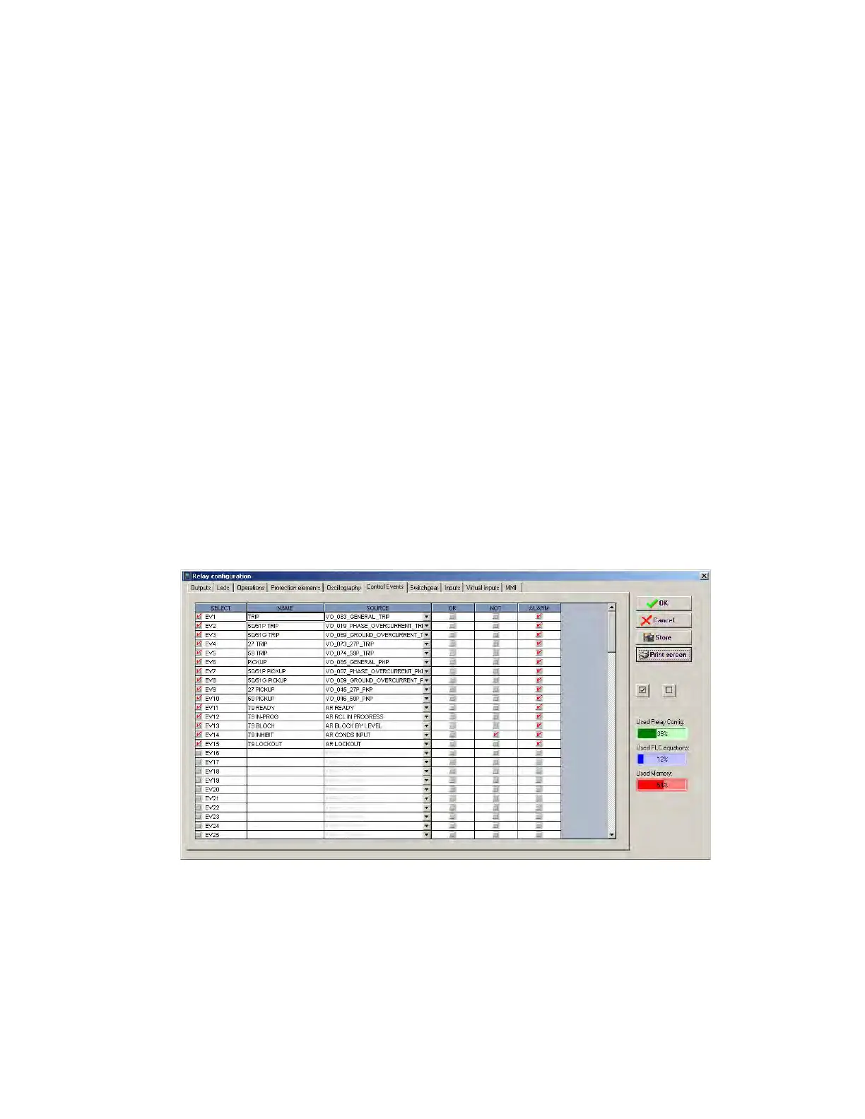
Figure 5-52: Control events configuration