2-4 F650 DIGITAL BAY CONTROLLER GEK-106310-AF
2.3 OTHER DEVICE FUNCTIONS CHAPTER 2: PRODUCT DESCRIPTION
2.3 Other device functions
*This functionality is available from firmware version 7.00
** Maximum number of events can vary depend on firmware version. See details in section 2.5.3.3
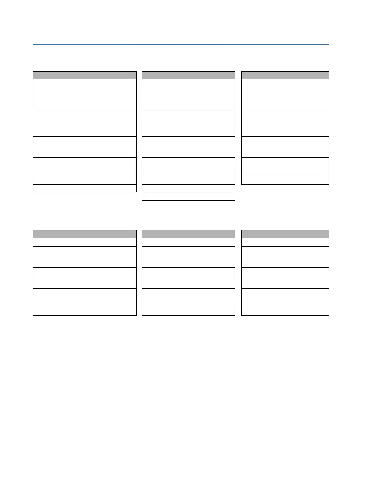
INPUTS/OUTPUTS METERING COMMUNICATIONS
9 Analog Inputs:
5 current inputs (3 for phases, 1 for ground, 1
for sensitiv
e ground),
4 voltage inputs (3 for phases, 1 for busbar or
auxil
iary voltage)
Metering Current for phases, ground and
s
ensitive ground inputs
Front RS232 port, USB port in HMI
option E, Two rear RS485/fibre optic
ports, 10/100 TX and 100 FX Mbps
Ethernet port
Digital Programmable Contact Inputs (up to
64)
Voltages phase to phase and phase to
gr
ound
ModBus Communications RTU and
over TCP/IP
Digital Programmable Contact Outputs (up to
16)
Real, Reactive and Apparent Power and
Po
wer Factor
DNP Multimaster (3.0 Level 2)
32 Latched Virtual Inputs
32 Self-Reset Virtual Inputs
Three Phase Energy IEC 870-5-104
Virtual Outputs (up to 512) Frequency ModBus User Map
Tripping and closing circuit supervision Sequence components of currents and
v
oltages
IEC 61850 protocol
Remote Inputs/Outputs (GSSE and GOOSE
messag
es)
Pulse Counters IEC 870-5-103 protocol
Analog Inputs (dCmA) Analog Comparators
*Digital Counters
USER INTERFACE RECORDS OTHERS
Alphanumerical display (4x20) Data Logger
Breaking Arcing Current (I
2
t)
Graphic display (16 x 40) Demand Breaker Control
User Programmable LEDs (15) Event Recorder (up to 128 configurable
ev
ents)
IRIG-B synchronization/SNTP/
IEEE 1588
User Programmable Keys (up to 5) Fault Locator and Fault report (up to 10
re
cords)
Logic Equations (PLC Editor)
Easy menu management Oscillography (up to 20 records) Operations (up to 24)
Configurable One-Line Diagram (Graphic
mod
el only)
Snapshot Events (up to 1023)** Web Server Application
Phasor Diagram (available in EnerVista 650
Setup)