5-98 F650 DIGITAL BAY CONTROLLER GEK-106310-AF
5.4 PROTECTION ELEMENTS CHAPTER 5: SETPOINTS
Rate of Change Function: This setting allows enabling or disabling the frequency rate of change element.
Freq rate trend: This setting allows to configure the element in order to answer to increasing,
decreasing or both directions frequency changes.
Freq. Rate Pickup: This setting defines the value to operate the element. If Direction is set as "Increasing",
element operates when df/dt > Pickup Level, if set as "Decreasing" when -df/dt >
Pickup Level, if set as both when |df/dt| > Pickup Level.
Freq. Rate OV supv: This setting defines the minimum required voltage. Under this level, the frequency rate
of change element is blocked. This is the percentage of the nominal voltage (adjust in
general settings). Voltage used as reference is line voltage (see frequency reference
setting in general settings).
Freq rate Min: This setting defines the minimum frequency required in this unit to be enabled. For
any value under this level the element is disabled.
Freq rate Max: This setting defines the maximum frequency allowed in this unit to be enabled. For
any value above this level the element is disabled.
Freq rate Delay: Time that the element must remain picked up before it operates.
Snapshot events: The snapshot event setting enables or disables the snapshot event generation for this
element.
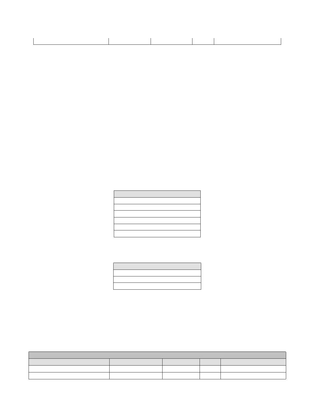
The frequency rate of change actual values can be viewed at Actual> Status > Control Elements > Frequency:
Table 5-65: Frequency rate of change status
The block signals for the frequency rate of change element can be viewed at: Actual> Status > Protection > Protection
Blocks:
Table 5-66: Frequency rate of change blocks
5.4.11 Miscellaneous elements
5.4.11.1 Broken conductor
F650 incorporates a broken or fallen conductor detection function. The relay uses the ratio between the negative
sequence current, I
2
, and the positive sequence current I
1
. In normal and balanced load situations, this ratio is zero, while
in severe load fault conditions, an unbalance is produced and this ratio increases.
Snapshot Events Generation Snapshot Events ENABLED N/A [DISABLED – ENABLED]
FREQUENCY RATE OF CHANGE STATUS
FREQ RATE1 PKP
FREQ RATE1 OP
FREQ RATE2 PKP
FREQ RATE2 OP
FREQ RATE3 PKP
FREQ RATE3 OP
FREQUENCY RATE OF CHANGE BLOCKS
FREQ RATE1 BLOCK
FREQ RATE2 BLOCK
FREQ RATE3 BLOCK
SETPOINT > PROTECTION ELEMENTS >SETTING GROUP X > MISCELLANEOUS > BROKEN CONDUCTOR
setting Description Name Default Value Step Range
Function permission Function DISABLED N/A [DISABLED – ENABLED]
Tap Level in percentage of I2/I1 Tap 20.0 0.1% [20.0 : 100.0]