CHAPTER 5: SETPOINTS 5.4 PROTECTION ELEMENTS
GEK-106310-AF F650 DIGITAL BAY CONTROLLER 5-61
5.4.3.3 Phase directional element (67P)
The Phase directional element (67P) provides independent elements for each phase, and determines the direction of the
current both in permanence and in fault condition.
Its main function is to apply a blocking signal to the overcurrent elements to prevent their operation when the current is
flowing in a certain direction. In order to determine the direction of the current, the element uses phase current values as
operation magnitude, and phase-to-phase voltage values as polarization magnitude. This means that in order to polarize a
phase, we use the phase-to-phase voltage of the other two phases, known as crossed polarization. To increase security for
three phase faults very close to the VTs used to measure the polarizing voltage, a voltage memory feature is incorporated.
This feature remembers the measurement of the polarizing voltage 3 cycles back from the moment when the voltage has
collapsed below the “polarizing voltage threshold”, and uses it to determine direction. The voltage memory remains valid
for a maximum of 3 seconds after the voltage has collapsed. This time is configurable.
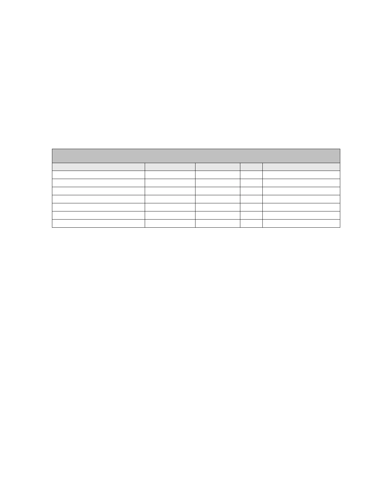
The following table describes the phase directional element settings.
Function: This setting allows enabling or disabling the corresponding directional element.
MTA: The MTA setting corresponds to the Torque angle, which is the rotation applied to
phase-to-phase crossed voltage.
Direction: This setting allows selecting the area for the directional element to operate, either
forward or reverse.
Block Logic: This setting allows selecting either permission or block, depending on the logic to be
applied upon expiration of voltage memory.
Polarization Voltage Threshold: This is the minimum voltage considered for the direction calculation. Under this setting,
memory voltage is used.
Snapshot Events: The snapshot event setting enables or disables the snapshot event generation for the
phase directional elements.
Voltage Memory Time: This is the time voltage memory is considered as valid and used for direction
calculation when polarization voltage collapses.
Phase directional element is an independent Protection element that provides block and Operation signals for each phase.
These signals can be monitored both through the relay HMI or using EnerVista 650 Setup at “Actual > Status > Protection
> Phase Current”
SETPOINT > PROTECTION ELEMENT > SETTING GROUP X > SETPOINT GROUP X > Phase Current > Phase Directional >
Phase Directional 1> Phase Directional 2 > Phase Directional 3
setting Description Name Default Value Step Range
Function permission Function DISABLED N/A [DISABLED – ENABLED]
Maximum Torque Angle MTA 45º 1 Deg [-90 : +90]
Operation Direction Direction FORWARD N/A [FORWARD – REVERSE]
Block logic Block Logic PERMISSION N/A [BLOCK – PERMISSION]
Polarization voltage threshold Pol V Threshold 40 1 V [0 : 300]
Snapshot event generation Snapshot Events ENABLED N/A [DISABLED – ENABLED]
Voltage Memory Time Voltage Memory time 0,00 s [0,00: 3,00]