5-56 F650 DIGITAL BAY CONTROLLER GEK-106310-AF
5.4 PROTECTION ELEMENTS CHAPTER 5: SETPOINTS
5.4.3 Phase current
The F650 Phase current menu incorporates the following overcurrent elements:
Phase time overcurrent (51PH/51PL)
Phase instantaneous overcurrent (50PH/50PL)
Phase directional overcurrent (67P)
Thermal Model (49)
5.4.3.1 Phase time delayed overcurrent elements – phase high/low (51Ph/51pl)
The phase overcurrent element (51P) can be configured in Enervista 650 Setup at Setppoint> Protection Element>Setting
Group X>Phase Current.
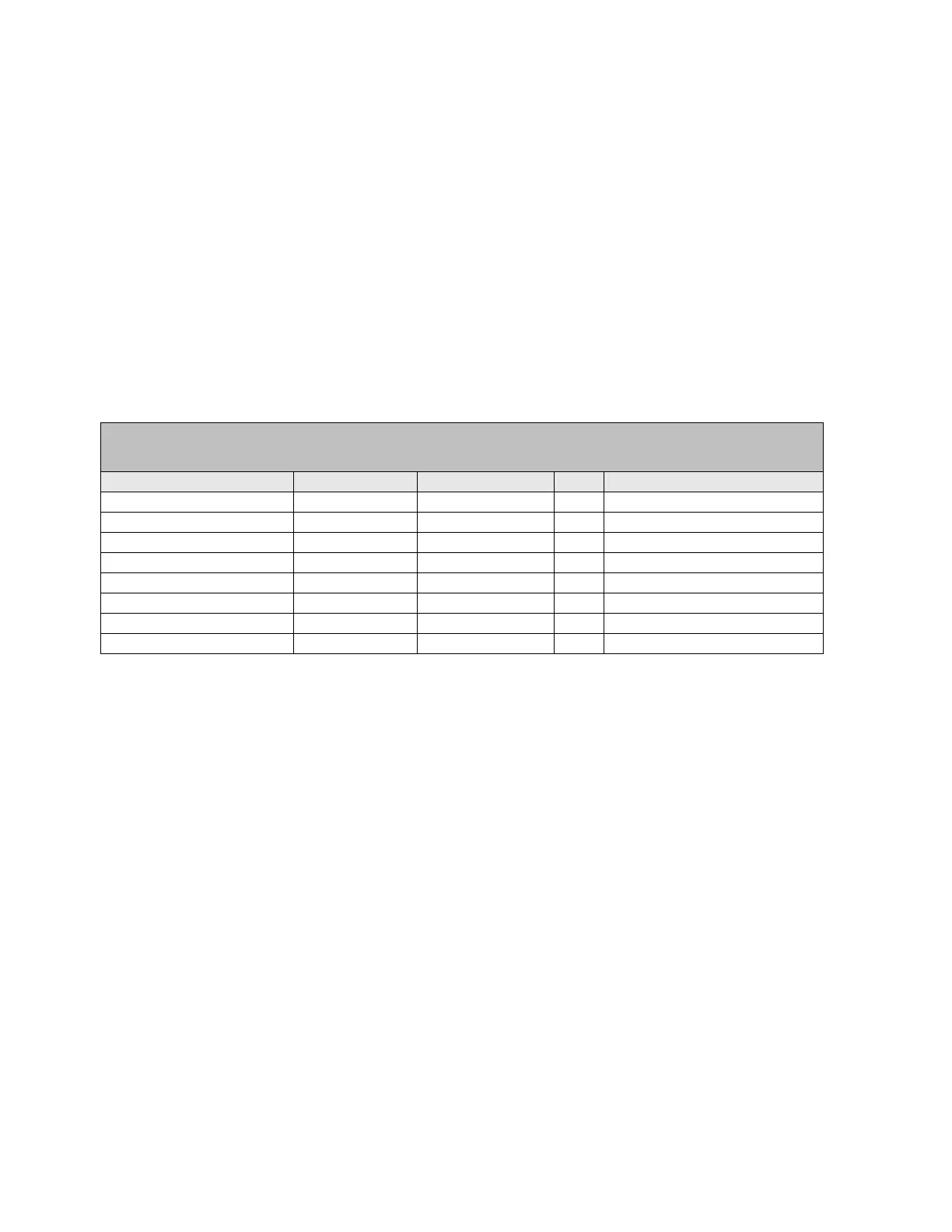
Table 5-31: Phase time overcurrent settings
The phase overcurrent element (51P) operates in a time period that depends on the applied current and on the set curve.
Possible outputs for the protection element logic are the pickup and tripping signals independent for each phase, and the
general element pickup and tripping signals.
Function: This setting allows enabling or disabling the corresponding directional element.
Input: The phase current input may be selected as fundamental phasor magnitude or total waveform
RMS magnitude as required by the application.
Pickup Level: This setting allows selecting the current level for the Phase Time Overcurrent element to
operate. The PICKUP setting of the element can be dynamically reduced by a VOLTAGE
RESTRAINT feature
Curve: This setting allows to select the curve that want to be use to operate this element. If the element
Curve is set as Definite Time, then the TD Multiplier setting is used to define both the Operation
time and, in case of selecting Linear reset, the Reset time of the element.
TD Multiplier: This setting allows the curve to be shifted up or down on the time-current characteristic curve.
This allows configuration of the relay depending on network selectivity
Reset: The element reset can be selected between Instantaneous and Linear (timed according to the
corresponding equation).
Voltage Restraint: As mention above, the pickup current magnitude can be dynamically reduced depending on
the existing voltage value. This is done using the Voltage Restraint setting. The pickup current
level is proportional to the phase-to-phase voltage measured according to a coefficient shown
on Figure 5–5:.This is accomplished via the multipliers (Mvr) corresponding to the phase-phase
voltages of the voltage restraint characteristic curve; the pickup level is calculated as ‘Mvr’
times the ‘Pickup’ setting. In the figure, Vpp is the phase-to-phase voltage, and VT Nominal is the
rated voltage set under General settings (refer to section 5.3.1)
SETPOINT> PROTECTION ELEMENT> SETTING GROUP X > Phase Current >
> Phase TOC High > Phase TOC High 1> Phase TOC High 2 > Phase TOC High 3
> Phase TOC Low > Phase TOC Low 1 > Phase TOC Low 2 > Phase TOC Low 3
setting Description Name Default Value Step Range
Function permission Function DISABLED N/A [DISABLED – ENABLED]
Input type Input PHASOR(DFT) N/A [PHASOR – RMS]
Pickup level Pickup Level 1.00 0.01 A [0.05 : 160.00]
Curve shape Curve IEEE Ext Inv N/A [See list of curves]
Time Dial TD Multiplier 1.00 0.01 s [0.00 : 900.00]
Reset type Reset INSTANTANEOUS N/A [INSTANTANEOUS – LINEAR]
Voltage Restraint Voltage Restraint DISABLED N/A [DISABLED – ENABLED]
Snapshot Event generation Snapshot Events ENABLED N/A [DISABLED – ENABLED]