CHAPTER 5: SETPOINTS 5.4 PROTECTION ELEMENTS
GEK-106310-AF F650 DIGITAL BAY CONTROLLER 5-57
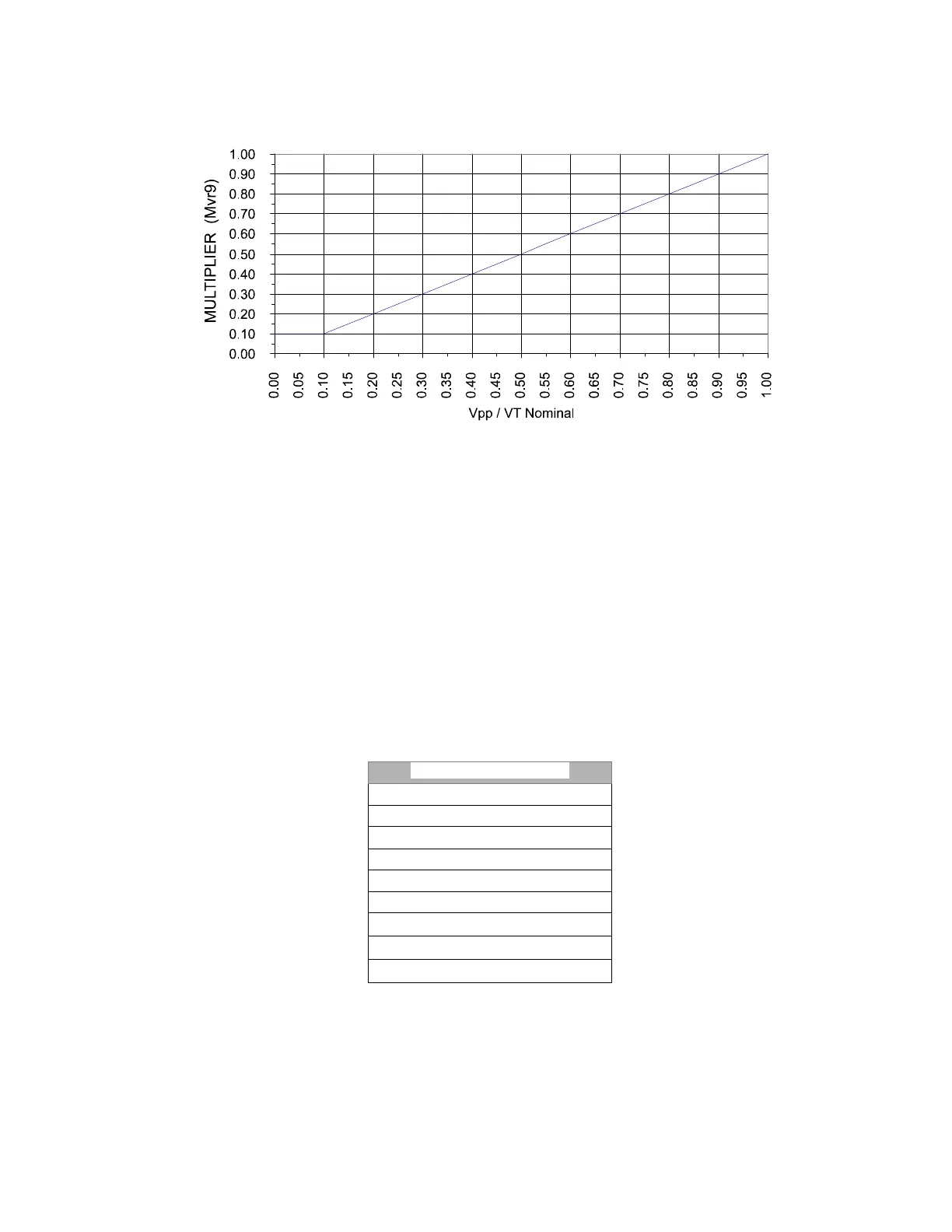
Figure 5-5: Voltage restraint characteristics
If the voltage restraint feature is disabled, the pickup level always remains at the value set in
the Pickup Level setting.
Snapshot Events: The snapshot event setting enables or disables the snapshot event generation for the phase
directional elements.
Phase time delayed overcurrent element is an independent Protection element that provides block and Operation signals
for each phase. Block signal status can be monitored through the relay HMI or using EnerVista 650 Setup at Actual >
Status > Protection > Protection Block and Operation Signal status at Actual > Status > Protection > Phase Current
The element incorporates independent block inputs for each phase. Block signals indicate blocked elements by an external
block input. When a particular signal is activated, the element is blocked. These inputs can be configured using Enervista
650 setup at Setpoint>Relay Configuration>Protection elements
Table 5-32: Block signal for the phase time delayed overcurrent element
When the element is blocked, the tripping time counter is reset to 0. This feature allows the use of this input to
instantaneously reset the protection element timing
BLOCK SIGNALS FOR 51P
PH TOC1 HIGH A BLK
PH TOC1 HIGH B BLK
PH TOC1 HIGH C BLK
PH TOC2 HIGH A BLK
PH TOC2 HIGH B BLK
PH TOC2 HIGH C BLK
PH TOC3 HIGH A BLK
PH TOC3 HIGH B BLK
PH TOC3 HIGH C BLK