5-184 F650 DIGITAL BAY CONTROLLER GEK-106310-AF
5.10 LOGIC CONFIGURATION (PLC EDITOR) CHAPTER 5: SETPOINTS
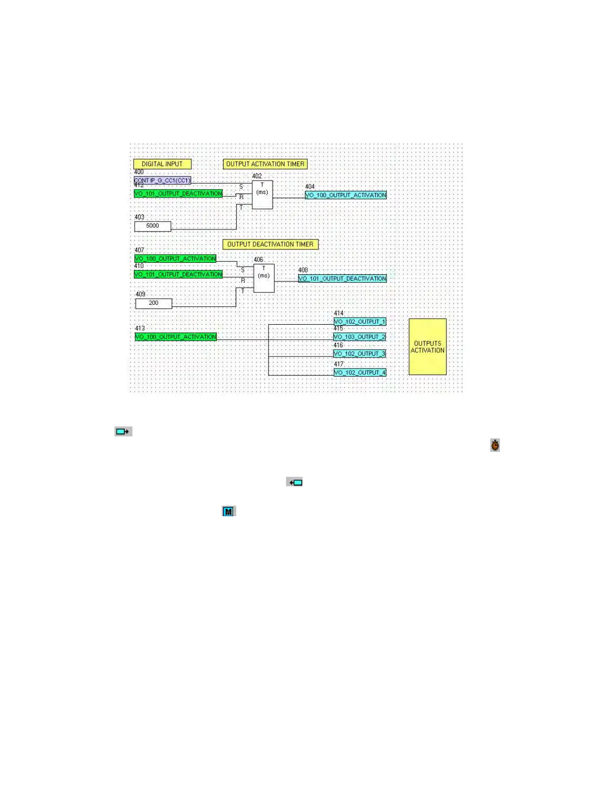
5.10.5 Application example
In this section a simple logic application is described step by step, a logic is such that keeping one digital input activated,
several outputs are activated and deactivated in a time window (outputs remain activated for 200 ms and deactivated for
5 ms). See the following figure:
Figure 5-59: Logic example
Go to the main menu and select File >New project, create a new project and select an input in the icons toolbar on the top
of the window. This input is selected as a digital input among the several options for inputs that can be selected. This
input is the SET input for the first timer to launch the output activation signal. Click the icon related to the timer to insert
the timer on the project. The timer has three inputs (S=set, R=reset and T=timing input)
The reset signal of the first timer is a virtual output called output_deactivation that has been created as an output of
another second timer. This signal is selected as an output
The timing signal for the first timer is a mask provided by the application, in which the time in milliseconds must be entered
in order to configure the timer time delay.
After creating the first timer, the second one for output deactivation is made. The set signal is the virtual output created as
an output of the first timer (VO_100_OUTPUT_ACTIVATION), the reset signal is the output of the second timer
(VO_100_OUTPUT_DEACTIVATION), the time delay is set as 200 ms.
Once the timing logic (timer 1 + timer 2) has been created, the activation signal (VO_100_OUTPUT_ACTIVATION) is linked to
several virtual outputs. Therefore, virtual outputs (VO_102_OUTPUT_1, VO_103_OUTPUT_2, VO_104_OUTPUT_3,
VO_105_OUTPUT_4) are activated if the CONT IP_G_CC1(CC1) variable is set to 1. Once the VO_100_OUTPUT_ACTIVATION
is active, it is deactivated after 200 ms, and remains deactivated for 5 seconds. This process is repeated while the digital
input is active.
To finish the process the logic must be compiled (Run >Compile) and the equations sent to the relay (Run >Send Equations
to relay) to start working with the new logic.