CHAPTER 5: SETPOINTS 5.3 SYSTEM SETUP
GEK-106310-AF F650 DIGITAL BAY CONTROLLER 5-37
5.3.4.1 Breaker maintenance
To consider used breakers, the relay allows to set initial I
2
t values as well as an initial number of operations, in order to take
into account previous breaker operations, as well as operations produced during testing. Breaker maintenance
parameters can be set in the breaker maintenance menu.
In this group of settings, the start values of the breaker Counters can be set.
These Counters allow the breaker Maintenance. They are used to accumulate the breaker aging produced by a trip or a
breaker opening. In order to incorporate the breaker’s history, in case of used breakers, the system allows assigning an
initial value to accumulated amperes, and to the number of opening and closing operations.
To supervise breaker aging, S(KI)
2
t accumulated values are calculated and stored for each phase in each opening. If the
rated current is not exceeded, as in the case of a manual opening command, without fault current, the relay uses the rated
current instead of the measured value.
(KI)
2
t value is accumulated and maintained in independent Counters for each phase. Counters can be accessed through
the local HMI as well as through the EnerVista 650 Setup software. The element incorporates a setting to select the
integration time ((KI)
2
t Integ. Time).
The signals associated with the opened or closed status of the breaker can be monitored at Actual > Status > Breaker
Table 5-16: Breaker status
The signals associated with breaker maintenance can be monitored at Actual > Status > Records Status > Breaker
Maintenance, and they are as follows:
Table 5-17: Breaker maintenance status
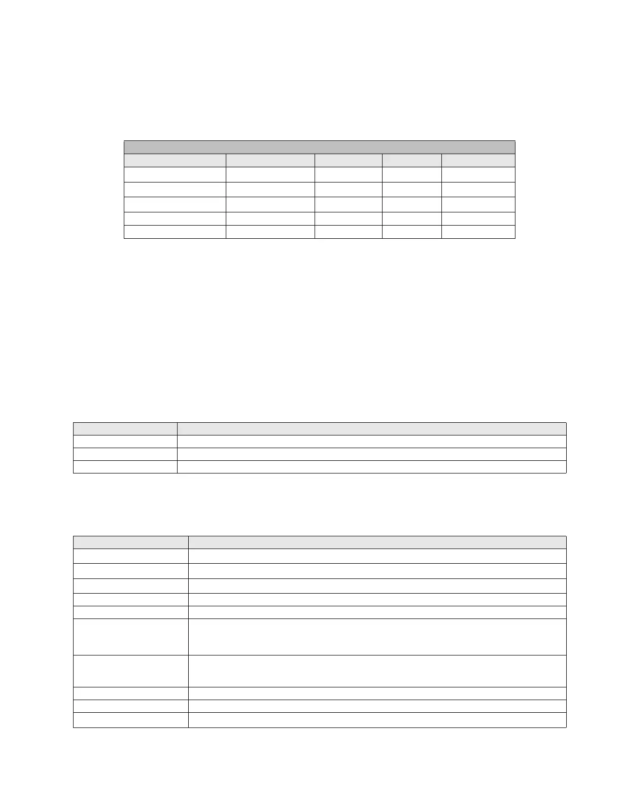
Setpoint > System Setup > Breaker > Breaker Maintenance
setting Description Name Default Value Step Range
(KI)
2
t Counter Phase A (KI)
2
t BKR Ph A Cnt
0.00
0.01 (KA)
2
s
[0.00 : 9999.99]
(KI)
2
t Counter Phase B (KI)
2
t BKR Ph B Cnt
0.00
0.01 (KA)
2
s
[0.00 : 9999.99]
(KI)
2
t Counter Phase C (KI)
2
t BKR Ph C Cnt
0.00
0.01 (KA)
2
s
[0.00 : 9999.99]
Openings counter BKR Openings Cnt 0 1 [0 : 9999]
Closings counter BKR Closings Cnt 0 1 [0 : 9999]
BREAKER STATUS DESCRIPTION
BREAKER OPEN Breaker in open position.
BREAKER CLOSED Breaker in close position
BREAKER UNDEFINED Breaker undefined
BREAKER MAINTENANCE DESCRIPTION
(KI)
2
t PHASE A ALARM
This signal activates when the set value for phase A is exceeded.
(KI)
2
t PHASE B ALARM
This signal activates when the set value for phase B is exceeded.
(KI)
2
t PHASE C ALARM
This signal activates when the set value for phase C is exceeded.
BKR OPENINGS ALARM Relay total Number of Openings alarm
BKR OPEN 1 HOUR ALRM Relay total Number of Openings in one hour alarm
RESET (KI)
2
t COUNTERS (KI)
2
t Counters reset signal. This signal is configured at Setpoint > Relay Configuration > Protection
Elements, and it is used for resetting the (KI)
2
t counter through the corresponding signal, command,
digital input, etc.
RESET BKR COUNTERS Reset signal for the Opening and Closing Counters. This signal is configured at Se
tpoint > Relay
Configuration > Protection Elements, and it is used for resetting the breaker Opening and closing
counters.
BREAKER OPENINGS Number of Breaker openings
BREAKER CLOSINGS Number of Breaker closings
(KI)
2
t PHASE A Accumulated (KI)
2
t value for phase A ((KI)
2
t Counter for Phase A)