CHAPTER 6: ACTUAL VALUES 6.4 INPUTS / OUTPUTS
GEK-106310-AF F650 DIGITAL BAY CONTROLLER 6-45
6.4 Inputs / outputs
Digital inputs and outputs are located in the same board. Depending on the relay model, the number of inputs and outputs
varies.
6.4.1 Contact inputs
Actual > Inputs/Outputs > Contact inputs > Board X (being X the corresponding board in each case).
On the inputs screen, the LED associated with the activated input lights in green, if an input is not activated, the LED does
not light up. The Board X Status LED indicates the status of the board; it is lit up if the board is correct and the
communication or the Relay model is appropriate.
Table 6-39: Contact input activation signals
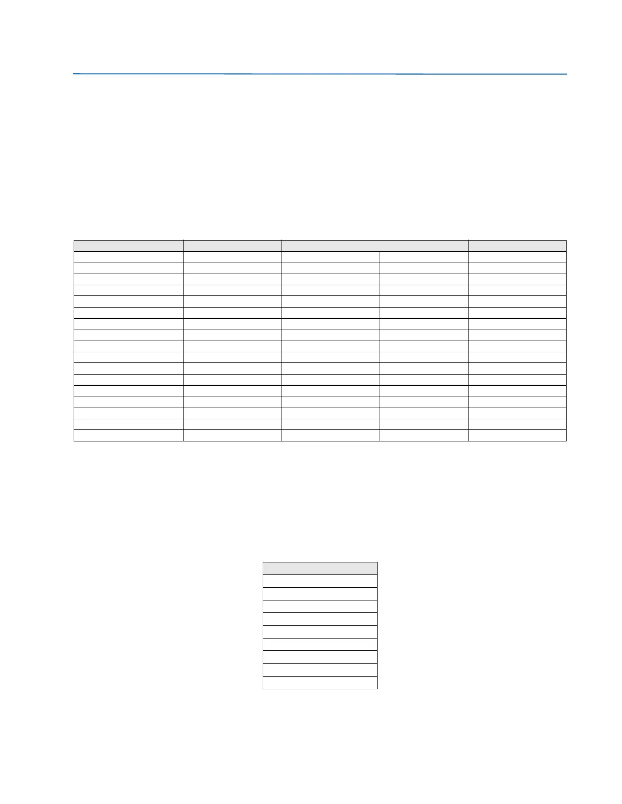
6.4.2 Contact output status
Actual > Inputs/Outputs > Contact Output Status > Board X (being X the corresponding board in each case).
The corresponding Outputs screen displays the activation of a contact output by lighting in green the associated LED.
Boards types 1 and 2 have both 8 outputs, so the representation is the same for both types as shown in the table below.
This screen shows the real status of the contact output, which corresponds to the transformation of the output activation
signal (Contact output operate), by the logic applied to this output in Setpoint > Inputs/Outputs >Contact I/O > Board X
NOTE: Both in the outputs menu as in the rest of menus available in “Actual”, the user can view several screens at the
same time to facilitate analysis.
CONTACT INPUTS TYPE 1 CONTACT INPUTS TYPE 2 CONTACT INPUTS TYPE 4 CONTACT INPUTS TYPE 5
CONT IP_X_CC1 (CC1) CONT IP_X_CC1 (CC1) CONT IP_X_CC1 (CC1) CONT IP_X_CC17 (CC17) CONT IP_X_CC1 (CC1)
CONT IP_X_CC2 (CC2) CONT IP_X_CC2 (CC2) CONT IP_X_CC2 (CC2) CONT IP_X_CC18 (CC18) CONT IP_X_CC2 (CC2)
CONT IP_X_CC3 (CC3) CONT IP_X_CC3 (CC3) CONT IP_X_CC3 (CC3) CONT IP_X_CC19 (CC19) CONT IP_X_CC3 (CC3)
CONT IP_X_CC4 (CC4) CONT IP_X_CC4 (CC4) CONT IP_X_CC4 (CC4) CONT IP_X_CC20 (CC20) CONT IP_X_CC4 (CC4)
CONT IP_X_CC5 (CC5) CONT IP_X_CC5 (CC5) CONT IP_X_CC5 (CC5) CONT IP_X_CC21 (CC21) CONT IP_X_CC5 (CC5)
CONT IP_X_CC6 (CC6) CONT IP_X_CC6 (CC6) CONT IP_X_CC6 (CC6) CONT IP_X_CC22 (CC22) CONT IP_X_CC6 (CC6)
CONT IP_X_CC7 (CC7) CONT IP_X_CC7 (CC7) CONT IP_X_CC7 (CC7) CONT IP_X_CC23 (CC23) CONT IP_X_CC7 (CC7)
CONT IP_X_CC8 (CC8) CONT IP_X_CC8 (CC8) CONT IP_X_CC8 (CC8) CONT IP_X_CC24 (CC24) CONT IP_X_CC8 (CC8)
CONT IP_X_CC9 (Va_COIL1) CONT IP_X_CC9 (CC9) CONT IP_X_CC9 (CC9) CONT IP_X_CC25 (CC25) CONT IP_X_CC9 (CC9)
CONT IP_X_CC10 (Vb_COIL1) CONT IP_X_CC10 (CC10) CONT IP_X_CC10 (CC10) CONT IP_X_CC26 (CC26) CONT IP_X_CC10 (CC10)
CONT IP_X_CC11 (Va_COIL2) CONT IP_X_CC11 (CC11) CONT IP_X_CC11 (CC11) CONT IP_X_CC27 (CC27) CONT IP_X_CC11 (CC11)
CONT IP_X_CC12 (Vb_COIL2) CONT IP_X_CC12 (CC12) CONT IP_X_CC12 (CC12) CONT IP_X_CC28 (CC28) CONT IP_X_CC12 (CC12)
CONT IP_X_CC13 (O7_SEAL) CONT IP_X_CC13 (CC13) CONT IP_X_CC13 (CC13) CONT IP_X_CC29 (CC29) CONT IP_X_CC13 (CC13)
CONT IP_X_CC14 (O8_SEAL) CONT IP_X_CC14 (CC14) CONT IP_X_CC14 (CC14) CONT IP_X_CC30 (CC30) CONT IP_X_CC14 (CC14)
CONT IP_X_CC15 (SUP_COIL1) CONT IP_X_CC15 (CC15) CONT IP_X_CC15 (CC15) CONT IP_X_CC31 (CC31) CONT IP_X_CC15 (CC15)
CONT IP_X_CC16 (SUP_COIL2) CONT IP_X_CC16 (CC16) CONT IP_X_CC16 (CC16) CONT IP_X_CC32 (CC32) CONT IP_X_CC16 (CC16)
BOARD X STATUS BOARD X STATUS BOARD X STATUS BOARD X STATUS
CONTACT OUTPUT STATUS
CONT OP_X_01
CONT OP_X_02
CONT OP_X_03
CONT OP_X_04
CONT OP_X_05
CONT OP_X_06
CONT OP_X_07
CONT OP_X_08
BOARD X STATUS