CHAPTER 5: SETPOINTS 5.5 CONTROL ELEMENTS
GEK-106310-AF F650 DIGITAL BAY CONTROLLER 5-103
5.5 Control elements
The F650 incorporates the following control elements:
Setting Group
Synchrocheck (25)
Autoreclose (79)
Breaker Failure (50BF)
VT Fuse Failure
Pulse Counters
Digital Counters
Analog Comparators
Max Number of starts
Cold Load Pickup
PLC Timer mask
60 CTS Failure
2nd Harmonic Inhibit
Note: for all control elements related to the breaker, it must be considered that all operations are performed considering
the status of the switchgear configured as breaker. In Setpoint > Relay Configuration > Switchgear up to 16 switchgear
elements can be configured to operate and be monitored, but only one of them can be configured as a breaker, for
monitoring, number of openings and closings counters, (KI)
2
t.
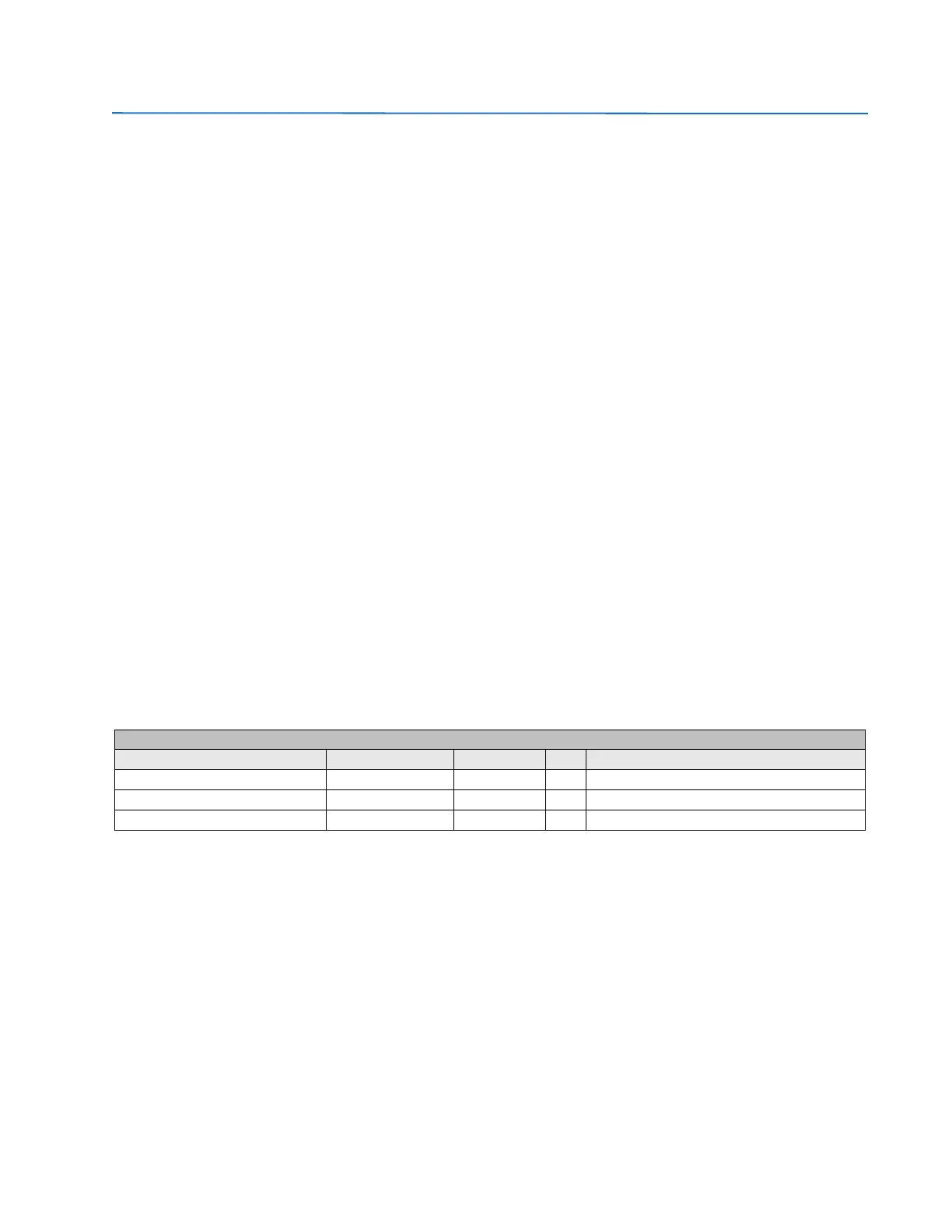
5.5.1 Setting group
The settings used for setting table management are located in Setpoint > Control Elements > Setting Group:
Table 5-72: Setting group settings
The snapshot event setting enables or disables the snapshot event generation for this element.
For more detailed information go to section 5.4.1 Available settings and setting groups
Setpoint > Control Elements > setting Group
setting Description Name Default Value Step Range
Setting Grouping Permission Function DISABLED N/A [DISABLED – ENABLED]
Active Group Active Group GROUP 1 N/A [GROUP 1 – GROUP 2 – GROUP 3]
Snapshot Event generation Snapshot Events ENABLED N/A [DISABLED – ENABLED]