5-42 F650 DIGITAL BAY CONTROLLER GEK-106310-AF
5.4 PROTECTION ELEMENTS CHAPTER 5: SETPOINTS
Setting Group settings are as follows:
Function: Possible values are: [DISABLED – ENABLED]
When this setting is disabled, the relay is working in single setting group mode, with all the available protection elements
working at the same time. If this function is enabled, the setting groups are enabled, and only the setting group indicated
by the Active Group setting is active.
Active group: Possible values are 1, 2 or 3.
The setting group selected by default is setting Group 1. This setting indicates which setting group is active (for this
purpose, the previous setting must be set as ENABLED)
The Relay incorporates several signals associated with the Protection elements grouping in tables. First, signals that
indicate the group activation:
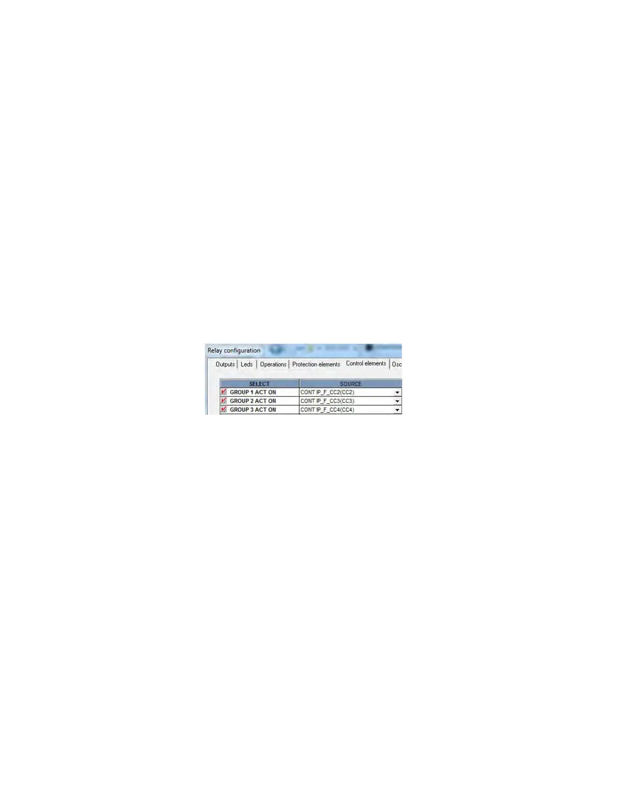
GROUP 1 ACT ON This signal produces the activation of setting group 1
GROUP 2 ACT ON This signal produces the activation of setting group 2
GROUP 3 ACT ON This signal produces the activation of setting group 3
These activation signals for the different setting groups are configured using EnerVista 650 Setup at Setpoint >
Relay Configuration > Control Elements as shown in the figure. For firmware prior to 7.00, these signal are located at
Setpoint > Relay Configuration > Protection Elements
Figure 5-3: Table change signals configuration example
The example above uses three digital inputs to perform the table selection, but it is possible to use any other logic signal in
the relay.
In case of using digital inputs, the user can select the setting table activating these digital inputs (which can come from the
PLC, or from a different relay, or from an auxiliary switch, for adaptive protection). This selection of the active group has
priority over the setting. If several signals are active at the same time, the highest one is taken as valid. For example, if
selection signals for both groups 1 and 2 are active, the active table is number 2.
The time used in the table change is one PLC logic scan cycle (5 ms typical), allowing a fast adaptation to system changes.
Another type of signals are block signals. These are internal relay signals that indicate which groups are active, and which
are blocked. For example, if the setting group function is enabled and setting group 1 has been set as active, block signals
from setting groups 2 and 3 are active, and the block signal that corresponds to group 1 is inactive because that group is
enabled.
Block signals are as follows:
GROUP 1 BLOCKED
GROUP 2 BLOCKED
GROUP 3 BLOCKED
All signals corresponding to setting Groups, both the activation and the block signals, are located in the Actual > Status >
Control Elements > setting Groups menu.