Volume Mode
Adjust the position of image B and C with trackball:
The position of image B and C in relationship to the reference image A is determined
through the Y-axis (= intersection line for image B) and through the X-axis
(= intersection line for image C). By positioning these two axes within the reference
image the corresponding parallel planes of B- and C-images are displayed
automatically.
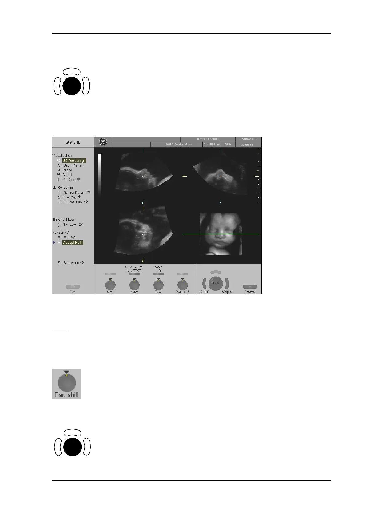
The selected reference image is sectional plane B
The spatial position of plane B in relationship to the displayed 3D image is always horizontal and also
normal to the 3D image display. Therefore the trace of image B is indicated by means of a horizontal
green
line within the 3D image.
Adjust the position of the green line within the 3D image:
Rotary control [Par. shift] enables a parallel shifting (up/down) of the green line and the
corresponding parallel planes of image B will be displayed automatically.
Adjust the position of image B and C with trackball:
The position of image A and C in relationship to the reference image B is determined
through the Y-axis (= intersection line for image A) and through the X-axis
(= intersection line for image C). By positioning these two axes within the reference
image the corresponding parallel planes of A- and C-images are displayed
automatically.
Voluson
®
730Pro - Basic User Manual
105831 Rev. 0 11-37