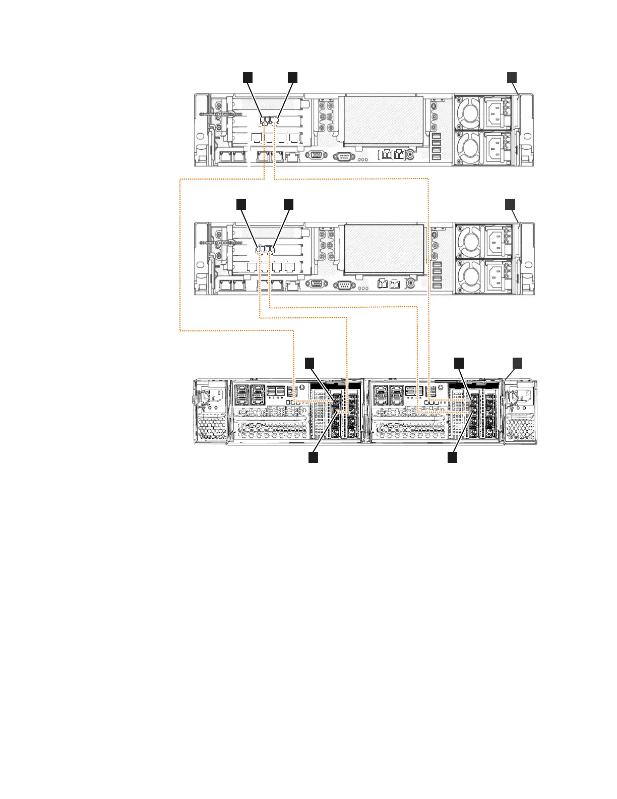
v ▌A▐ File module 1
v ▌B▐ File module 2
v ▌C▐ Storwize V7000 Gen2 control enclosure (2076-524)
v ▌1▐ File module 1 - Fibre Channel port 1
v ▌2▐ File module 1 - Fibre Channel port 2
v ▌3▐ File module 2 - Fibre Channel port 1
v ▌4▐ File module 2 - Fibre Channel port 2
v ▌5▐ Node canister 1 (left) - Fibre Channel port 1
v ▌6▐ Node canister 1 (left) - Fibre Channel port 2
v ▌7▐ Node canister 2 (right) - Fibre Channel port 1
v ▌8▐ Node canister 2 (right) - Fibre Channel port 2
Table 38 on page 75 describes the diagrams shown in Figure 41 on page 73 and
Figure 42.
32121 3
1
2
3
4
5
6
1
2
3
4
5
6
2
A
C
8
5
6
1
B
3
4
7
ifs000080
Figure 42. Connecting the file modules to a Storwize V7000 Gen2 control enclosure that has
a Fibre Channel interface adapter in PCI slot 2 of each node canister
74 Storwize V7000 Unified: Problem Determination Guide 2073-720

 Loading...


