EasyManuals Logo

IBM Storwize V7000 Unified Problem Determination Guide

IBM Storwize V7000 Unified
474 pages
To Next Page IconTo Next Page
To Previous Page IconTo Previous Page
Page #35 background imageLoading...
Page #35 background image
Enclosure end cap indicators
Storwize V7000 Unified enclosure end cap indicators vary, depending on the
generation of your control enclosure model.
Storwize V7000 Gen1
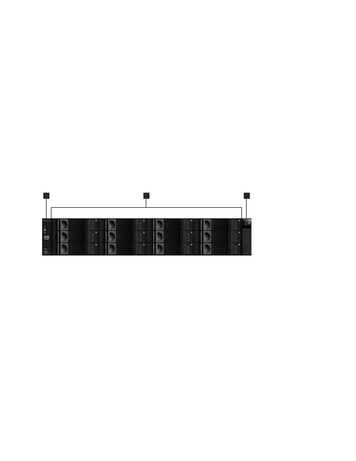
Figure 12 shows where the end caps are located on the front of an enclosure with
12 drives. The end caps are located in the same position for an enclosure with 24
drives.
1 Left end cap
2 Drives
3 Right end cap
Figure 13 on page 8 shows the indicators on the front of the enclosure end cap.
The left enclosure end caps for both enclosures are identical and contain only
indicators. The left enclosure end cap contains no controls or connectors. The right
enclosure end cap for both enclosures has no controls, indicators, or connectors.
svc00694
1
2
3
Figure 12. Storwize V7000 Gen1 12 drives and two end caps
Chapter 1. Storwize V7000 Unified hardware components 7

Table of Contents

Other manuals for IBM Storwize V7000 Unified

Questions and Answers:

Question and Answer IconNeed help?

Do you have a question about the IBM Storwize V7000 Unified and is the answer not in the manual?

IBM Storwize V7000 Unified Specifications

General IconGeneral
ModelIBM Storwize V7000 Unified
Storage TypeUnified Storage
RAID LevelsRAID 0, 1, 5, 6, 10
Form Factor2U
Drive Types SupportedSAS, SSD
Maximum Drives504
Network ProtocolsiSCSI, FC, FCoE
Drive Bays24 per enclosure
Host Interface8 Gb FC, 1 Gb/10 Gb iSCSI
File ProtocolsNFS, CIFS
Block ProtocolsiSCSI, Fibre Channel
TypeUnified Storage
Maximum Host Ports16
Operating System SupportVMware, Microsoft Windows, Linux, AIX
Data ServicesThin provisioning, replication
Power SupplyRedundant power supplies
Host Interfaces8 Gbps Fibre Channel, 10 Gbps iSCSI, 1 Gbps iSCSI

Related product manuals