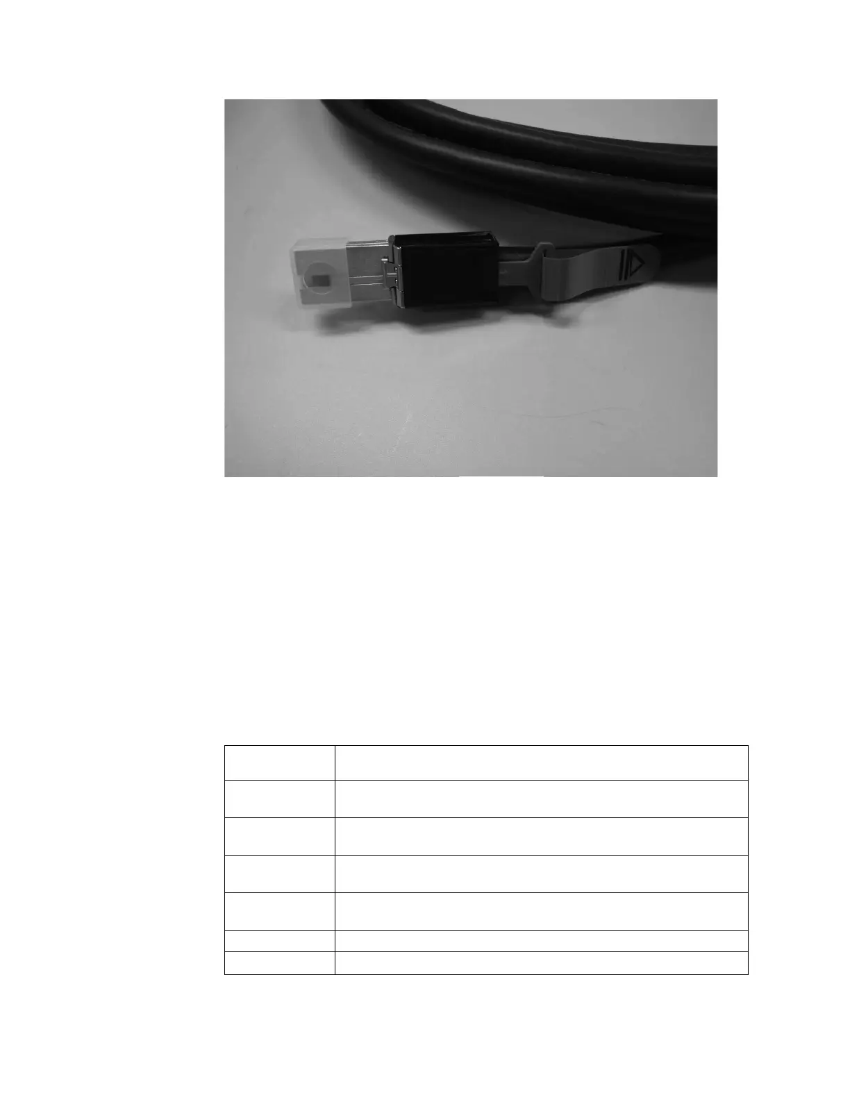
3. Plug the replacement cable into the specific port.
4. Ensure that the SAS cable is fully inserted. A click is heard when the cable is
successfully inserted.
Replacing a control enclosure chassis
Remove and replace a control enclosure chassis. This procedure only applies to
Storwize V7000 Gen1 control enclosure models.
About this task
Storwize V7000 Unified Gen1 refers to the enclosure models in the following table:
Table 110. Storwize V7000 Unified Gen1 model numbers
Machine
type/model Description
2076-112 Storwize V7000 Unified control enclosure for up to 12 3.5-inch (8.89
cm) drives
2076-124 Storwize V7000 Unified control enclosure for up to 24 2.5-inch (6.35
cm) drives
2076-312 Storwize V7000 Unified control enclosure for 3.5-inch drives (with two
10 Gbps iSCSI/FCoE Ethernet ports)
2076-324 Storwize V7000 Unified control enclosure for 2.5-inch drives (with two
10 Gbps iSCSI/FCoE Ethernet ports)
2076-212 Storwize V7000 Unified expansion enclosure for 3.5-inch drives
2076-224 Storwize V7000 Unified expansion enclosure for 2.5-inch drives
Figure 103. SAS cable
332 Storwize V7000 Unified: Problem Determination Guide 2073-720

 Loading...


