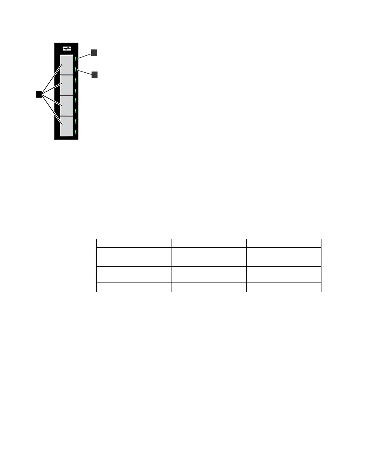
▌1▐ Fibre Channel 8 Gbps ports (x4)
▌2▐ Link-state LED (x4 - one for each port)
▌3▐ Speed-state LED (x4 - one for each port)
Fibre Channel host interface adapter indicators
Each Fibre Channel port has two green LED indicators. The link-state LED ▌2▐ is
above the speed-state LED ▌3▐ for each port. Consider the LEDs as a pair to
determine the overall link state, which is decoded in Table 17.
Table 17. Fibre Channel host interface adapter port-state LEDs
Link-state LED Speed-state LED Link state
OFF OFF Inactive
ON or FLASHING OFF Active low speed (2 Gbps)
ON or FLASHING FLASHING Active medium speed (4
Gbps)
ON or FLASHING ON Active high speed (8 Gbps)
One or two Fibre Channel interface adapters can be installed in each node canister.
They can be installed in slots 2 and 3 of the node canister. When a single interface
adapter is installed in either slot 2 or slot 3, the Fibre Channel ports on the adapter
are numbered 1, 2, 3, and 4.
Storwize V7000 2076-524 10 Gbps Fibre Channel over Ethernet/iSCSI host
interface adapter ports and indicators:
You have the option to install 10 Gbps Fibre Channel over Ethernet/iSCSI host
interface adapters for your Storwize V7000 2076-524 system, the adapter is
preinstalled in each node canister.
The 4 port FCoE/iSCSI host interface adapter is used for Fibre Channel over
Ethernet (FCoE) or Internet Small Computer System Interface (iSCSI) connections
to host systems or for Fibre Channel over Ethernet connections to host system or
storage systems. Each port can support simultaneous FCoE and iSCSI connections.
The Small Form-factor Pluggable (SFP) transceivers that are installed on the
adapter support data transfer speeds of 10 Gbps.
Figure 24. Fibre Channel ports and indicators
22 Storwize V7000 Unified: Problem Determination Guide 2073-720

 Loading...


