Replacing a Storwize V7000 Gen2 node canister memory module
(16 GB DIMM)
You can replace a faulty node canister memory module (16 GB DIMM) with a new
one received from CRU / FRU stock.
Procedure
1. Follow “Procedure: Removing a Storwize V7000 Gen2 node canister” on page
279 to disconnect and remove the node canister with the faulty memory.
2. Remove the lid of the canister, as described in “Procedure: Removing and
replacing the lid of a Storwize V7000 Gen2 node canister” on page 285.
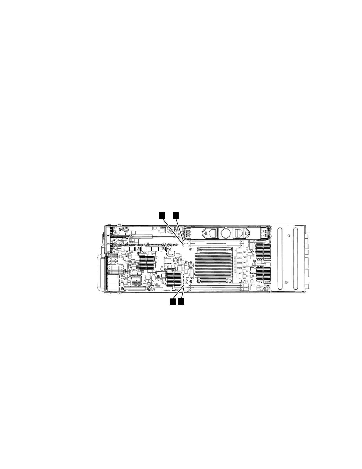
3. Locate the DIMM slot with the faulty DIMM. Slot 1 is next to the battery area.
Slot 2 is next to the processor. The slots are marked 1, 2 , 4, 3 as shown in
Figure 116.
4. Remove the faulty DIMM by applying gentle, outwards pressure
simultaneously to the retaining clips at each end of the DIMM slot until the
DIMM is levered out of the slot.
5. Touch the replacement DIMM packaging onto a metal area of the case, then
remove the replacement DIMM from its package.
6. Ensure that the retaining clips of the DIMM slot are open.
7. Gently place the DIMM in the slot, ensuring that the notches in the DIMM
align with the shape of the slot, as shown in Figure 116.
8. Apply even, firm, downwards pressure on the DIMM in its slot until the
retaining clips move inwards and engage the edges of the DIMM.
9. Ensure that the retaining clips are fully engaged with the edges of the DIMM.
Gently pull the DIMM upwards and ensure that it does not become
dislodged.
10. Replace the canister lid, as described in “Procedure: Removing and replacing
the lid of a Storwize V7000 Gen2 node canister” on page 285.
11. Reinstall the canister, as described in “Replacing a Storwize V7000 Gen2 node
canister” on page 295, into the enclosure from which it was removed in step 1.
The node canister starts.
12. Reconnect the cables to the canister, ensuring cables go into the same ports
from which they were removed in step 1.
13. When the canister is back online, check the event log for new events,
particularly events that relate to hardware changes.
Figure 116. Installing a Storwize V7000 2076-524 node canister memory module
370 Storwize V7000 Unified: Problem Determination Guide 2073-720
 Loading...


