EasyManuals Logo

IBM Storwize V7000 Unified Problem Determination Guide

IBM Storwize V7000 Unified
474 pages
To Next Page IconTo Next Page
To Previous Page IconTo Previous Page
Page #154 background imageLoading...
Page #154 background image
Procedure
1. Read the safety information that begins on page Safety and “Installation
guidelines” on page 94.
2. Remove all the cables that are connected to the front of the file module.
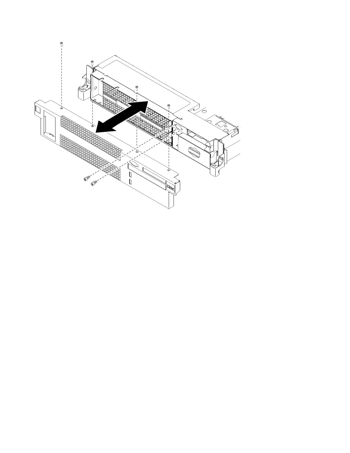
3. Remove the cable retention bolts from the VGA port.
4. Remove the screws from the bezel.
5. Rotate the top of the bezel away from the file module.
Installing the bezel
The following procedure is for a Tier 1 customer replaceable unit (CRU).
Replacement of Tier 1 CRUs is your responsibility. If IBM installs a Tier 1 CRU at
your request, you will be charged for the installation. Service agreements can be
purchased so that you can ask IBM to replace these units.
About this task
To install the bezel, complete the following steps.
v7000003
Figure 52. Removing the bezel
126 Storwize V7000 Unified: Problem Determination Guide 2073-720

Table of Contents

Other manuals for IBM Storwize V7000 Unified

Questions and Answers:

Question and Answer IconNeed help?

Do you have a question about the IBM Storwize V7000 Unified and is the answer not in the manual?

IBM Storwize V7000 Unified Specifications

General IconGeneral
ModelIBM Storwize V7000 Unified
Storage TypeUnified Storage
RAID LevelsRAID 0, 1, 5, 6, 10
Form Factor2U
Drive Types SupportedSAS, SSD
Maximum Drives504
Network ProtocolsiSCSI, FC, FCoE
Drive Bays24 per enclosure
Host Interface8 Gb FC, 1 Gb/10 Gb iSCSI
File ProtocolsNFS, CIFS
Block ProtocolsiSCSI, Fibre Channel
TypeUnified Storage
Maximum Host Ports16
Operating System SupportVMware, Microsoft Windows, Linux, AIX
Data ServicesThin provisioning, replication
Power SupplyRedundant power supplies
Host Interfaces8 Gbps Fibre Channel, 10 Gbps iSCSI, 1 Gbps iSCSI

Related product manuals