16. Turn the enclosure over again so that the top of the enclosure is facing
upward and the front is facing towards you.
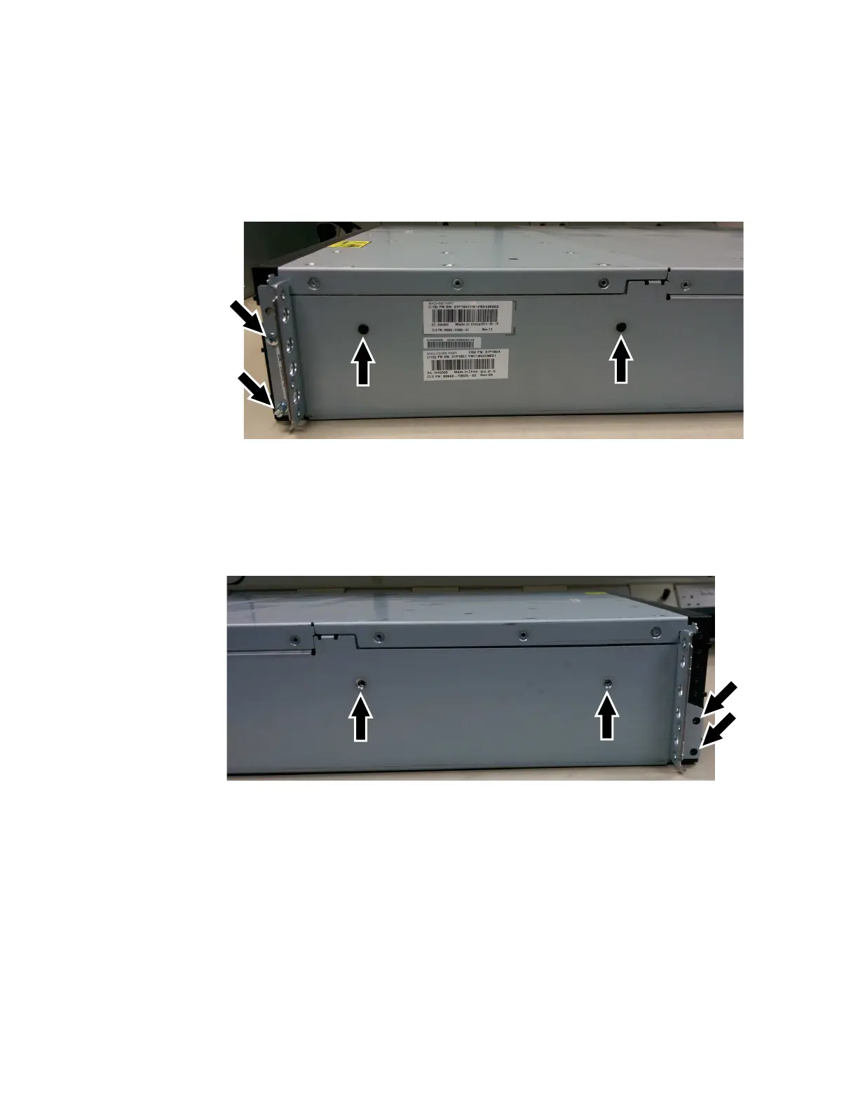
17. Remove the three screws and one screw-pin on the right side that secure the
midplane assembly to the enclosure. Label each screw to indicate the removal
location and place the screws aside. Figure 105 illustrates the location of the
screws and screw-pin on the right-side of the enclosure.
18. Remove the three screws and one screw-pin on the left side that secure the
midplane assembly to the enclosure. Label each screw to indicate the removal
location and place the screws aside. Figure 106 illustrates the location of the
screws and screw-pin on the left-side of the enclosure.
19. Remove the midplane assembly from the chassis by rotating up the midplane
assembly to about 45°, then withdraw the midplane assembly from the front
of the enclosure. Figure 107 on page 357 shows the midplane assembly at a 45
degree angle.
Figure 105. Right-side enclosure screws
Figure 106. Left-side enclosure screws
356 Storwize V7000 Unified: Problem Determination Guide 2073-720

 Loading...


