Table 85. Storwize V7000 Unified Gen1 model numbers (continued)
Machine
type/model Description
2076-312 Storwize V7000 Unified control enclosure for 3.5-inch drives (with two
10 Gbps iSCSI/FCoE Ethernet ports)
2076-324 Storwize V7000 Unified control enclosure for 2.5-inch drives (with two
10 Gbps iSCSI/FCoE Ethernet ports)
2076-212 Storwize V7000 Unified expansion enclosure for 3.5-inch drives
2076-224 Storwize V7000 Unified expansion enclosure for 2.5-inch drives
Storwize V7000 Unified Gen2 refers to the newer generation of enclosures in the
following table:
Table 86. Storwize V7000 Unified Gen2 model numbers
Machine
type/model Description
2076-524 Storwize V7000 Unified control enclosure, with up to 24 2.5-inch (6.35
cm) drives
2076-12F Storwize V7000 Unified expansion enclosure for up to 12 3.5-inch (8.89
cm) drives
2076-24F Storwize V7000 Unified expansion enclosure for 2.5-inch drives
Procedure: Understanding the Storwize V7000 Gen2 system
status from the LEDs
To determine the Storwize V7000 2076-524 system status using the LED indicators
on a control enclosure, use this procedure.
About this task
To understand the status of the I/O port at the rear of a control enclosure, refer to
the topic about Storwize V7000 2076-524 node canister ports and indicators that is
linked at the end of this topic.
Status indicators on the front of a control enclosure are described in the topic
about components in the front of the enclosure that is linked at the end of this
topic.
A detailed view of the system state is provided in the Monitoring sections of the
management GUI and by the service assistant. If neither the management GUI nor
the service assistant is accessible, use this procedure to determine the system status
using the LED indicators on the control enclosures.
The system status LEDs visible at the rear of each control enclosure can show one
of several states, as described in Table 87.
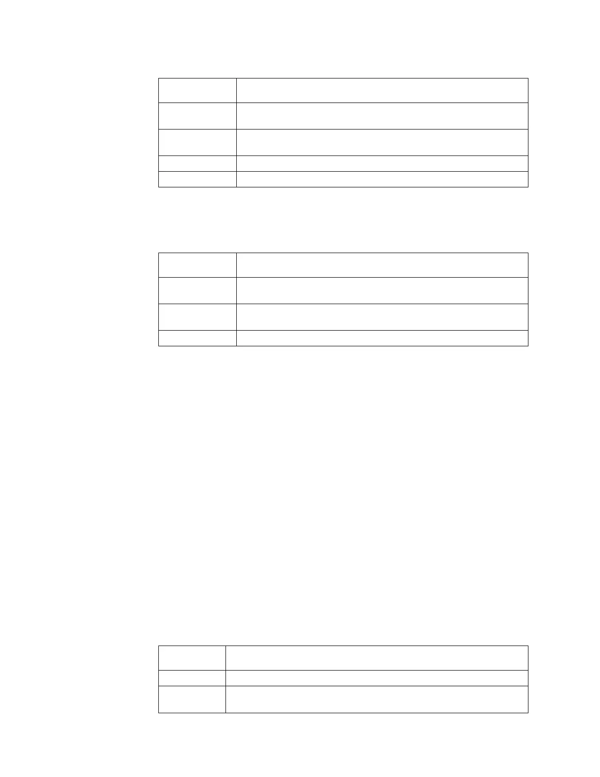
Table 87. LED state descriptions used in the Storwize V7000 2076-524 enclosure
State
description Detail
Off The LED is continuously not lit.
Flashing
slowly
The LED turns on and off at a frequency of 1 Hz: It is on for 500 ms, then
off for 500 ms, then repeats.
256 Storwize V7000 Unified: Problem Determination Guide 2073-720
 Loading...


