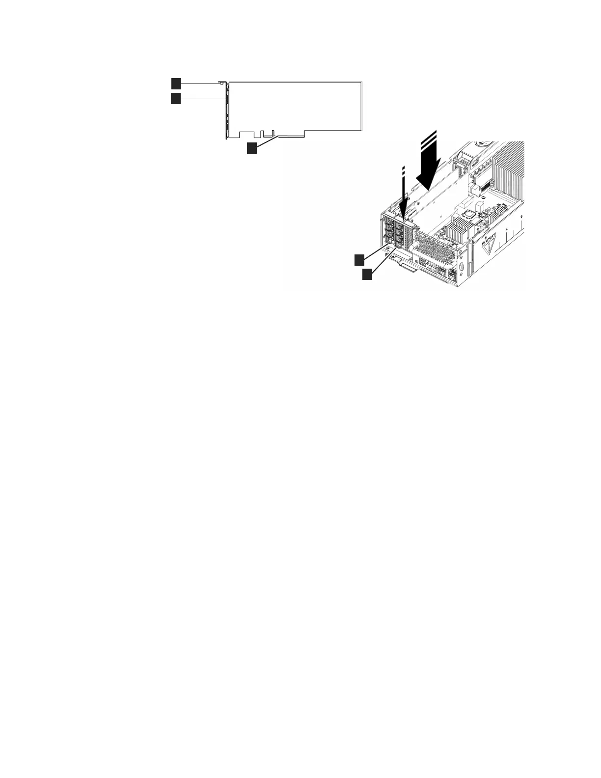
10. Check that the host interface adapter is installed squarely in its slot. If the
small tab of the mounting bracket is not positioned correctly, repeat steps 5 on
page 371 onward to install the adapter correctly.
11. Replace the canister lid, as described in “Procedure: Removing and replacing
the lid of a Storwize V7000 Gen2 node canister” on page 285.
12. If any SFP transceivers were removed from the rear-facing ports of the host
interface adapter at step 2 on page 371, ensure each one is reinstalled by
following the installation steps of “Replacing an SFP transceiver in a Storwize
V7000 2076-524 control enclosure” on page 302.
13. Reinstall the canister into the enclosure from which it was removed in step 1
on page 371 following “Replacing a Storwize V7000 Gen2 node canister” on
page 295. The node canister starts.
14. Reconnect the cables to the canister, ensuring cables go into the same ports
from which they were removed in step 1 on page 371.
15. When the canister is back online, check the event log for any new events
relating to hardware changes.
Replacing Storwize V7000 Gen2 host interface adapters in two
control enclosures concurrently
It is possible to reconfigure one node canister of each control enclosure at the same
time. During the procedure, both I/O groups (control enclosures) are online with
no redundancy, but the total maintenance period is reduced.
To replace host interface adapters in both control enclosures concurrently, use the
procedure for replacing the host interface adapter in a single enclosure, but
complete each step in both enclosures before continuing to the next step. Table 116
on page 374 shows how to sequence the step in each node. Work your way down
the table, completing each row before starting the next row.
For the procedure for replacing the host interface adapter in a single enclosure,
refer to the “Replacing a Storwize V7000 Gen2 host interface adapter” on page 371.
Figure 118. Installing the host interface adapter
Chapter 5. Control enclosure 373
 Loading...


