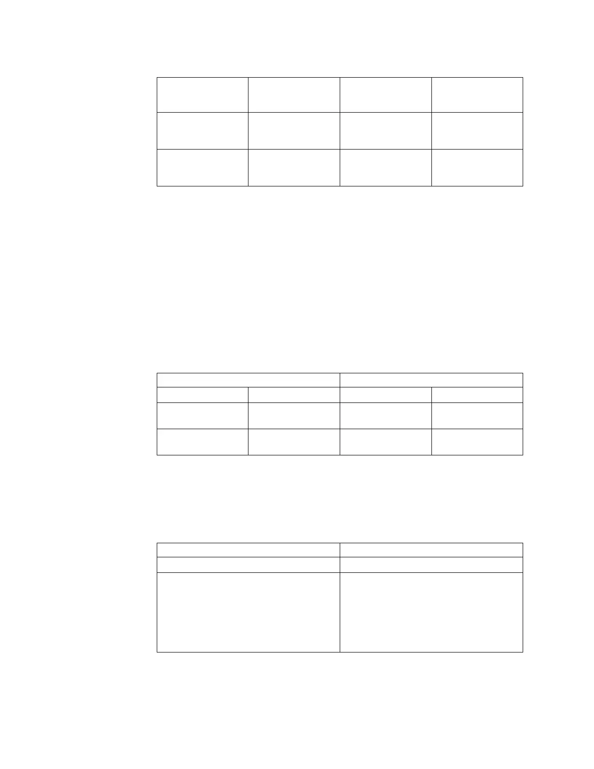
Table 39. Error code port location mapping (continued)
Error code Description
File Module Fibre
Channel Location
Storage Node
Canister Fibre
Channel Port
4B0803C Slow connection on
Fibre Channel
adapter 1, port 1.
PCI slot #2 – port 1
(right port when
facing rear of system)
Node canister 1, port
1. OR node canister
1, port 2.
4B0804C Slow connection on
Fibre Channel
adapter 1, port 2.
PCI slot #2 – port 2
(left port when facing
rear of system)
Node canister 2, port
1. OR node canister
2, port 2.
To enable the LED indicator for the node reporting the problem, use the
Monitoring > System page in the management GUI or follow this procedure:
1. Log onto the active file module via the CLI interface.
2. Run the command: locatenode #HOSTNAME on #SECONDS. HOSTNAME is the
hostname associated with the error... either mgmt001st001or mgmt002st001.
#SECONDS is the number of seconds for the LED indicator to be turned on.
Physical connection and repair:
Each file module has a dual port Fibre Channel adapter card located in PCI slot 2.
Both ports are used to connect to the Storwize V7000 system with a connection
going to each Storwize V7000 node canister.
Table 40. Fibre Channel cabling from the file module to the control enclosure.
File Module Node # 1 File Module Storage Node # 2
PCI slot #2, port 1 PCI slot #2, port 2 PCI slot #2, port 1 PCI slot #2, port 2
Connects to Storwize
V7000
Connects to Storwize
V7000
Connects to Storwize
V7000
Connects to Storwize
V7000
Node canister 2 –
Fibre Channel port 1
Node canister 1 –
Fibre Channel port 1
Node canister 2 –
Fibre Channel port 2
Node canister 1 –
Fibre Channel port 2
If a problem is detected with a Fibre Channel path between the storage node and
the control enclosure, check the LED indicators next to the Fibre Channel
connection ports on both the file module and the Storwize V7000 node canister.
Table 41. LED states and associated actions. For the Fibre Channel adapters on the file
module check the amber LED lights next to the port.
LED State Definition and Action
Solid amber LED This state indicates a good connection status.
Slow flashing amber LED This state indicates a good connection at the
Fibre Channel port but a broken connection
at the Storwize V7000 node canister. This
broken connection is most likely either a
Fibre Channel cable or the Fibre Channel
port is bad on the Storwize V7000 node
canister.
76 Storwize V7000 Unified: Problem Determination Guide 2073-720

 Loading...


