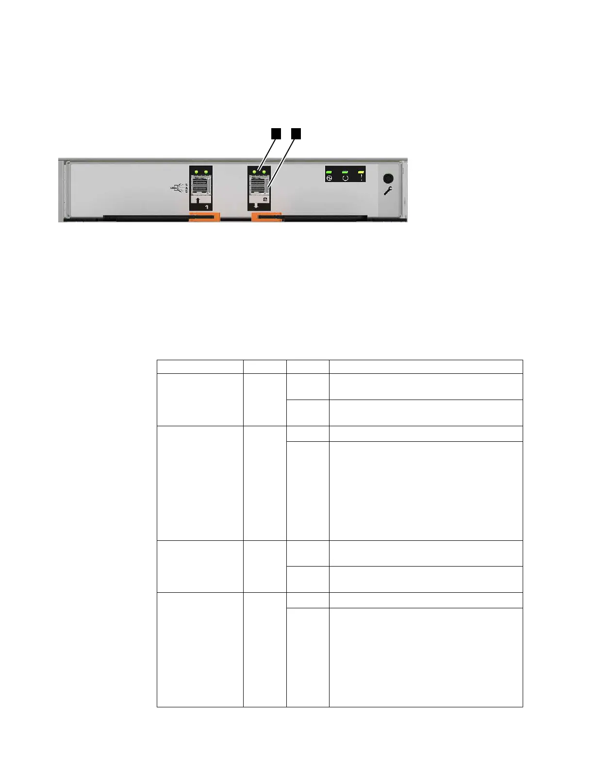
SAS ports are numbered at the bottom of the port, with 1 on the left and 2 on the
right, as shown in Figure 35. Use of port 1 is required. Use of port 2 is optional.
Each port connects four data channels.
Figure 35 has callouts to show the location of the LEDs and the port for SAS port
2:
▌1▐ Port 2 LEDs
▌2▐ Port 2 12 Gbps SAS port
Table 25 describes LED states for each of the two LEDs per SAS port. The link LED
is on the left of each set of ports.
Table 25. SAS port LEDs on the expansion canister
Name Color State Meaning
SAS Port 1 Link Green OFF No link connection on any phys (lanes). The
connection is down.
ON There is a connection on at least one phy. At
least one of the phys to that connector is up.
SAS Port 1 Fault Amber OFF No fault. All four phys have a link connection.
ON This can indicate a number of different error
conditions:
v One or more, but not all, of the 4 phys are
connected.
v Not all 4 phys are at the same speed.
v One or more of the connected phys are
attached to an address different from the
others
SAS Port 2 Link Green OFF No link connection on any phys (lanes). The
connection is down.
ON There is a connection on at least one phy. At
least one of the lanes to that connector is up.
SAS Port 2 Fault Amber OFF No fault. All four phys have a link connection.
ON This can indicate a number of different error
conditions:
v One or more, but not all, of the 4 phys are
connected.
v Not all 4 phys are at the same speed.
v One or more of the connected phys are
attached to an address different from the
others
Figure 35. SAS ports and LEDs at rear of expansion canister
32 Storwize V7000 Unified: Problem Determination Guide 2073-720

 Loading...


