EasyManuals Logo

IBM Storwize V7000 Unified Problem Determination Guide

IBM Storwize V7000 Unified
474 pages
To Next Page IconTo Next Page
To Previous Page IconTo Previous Page
Page #53 background imageLoading...
Page #53 background image
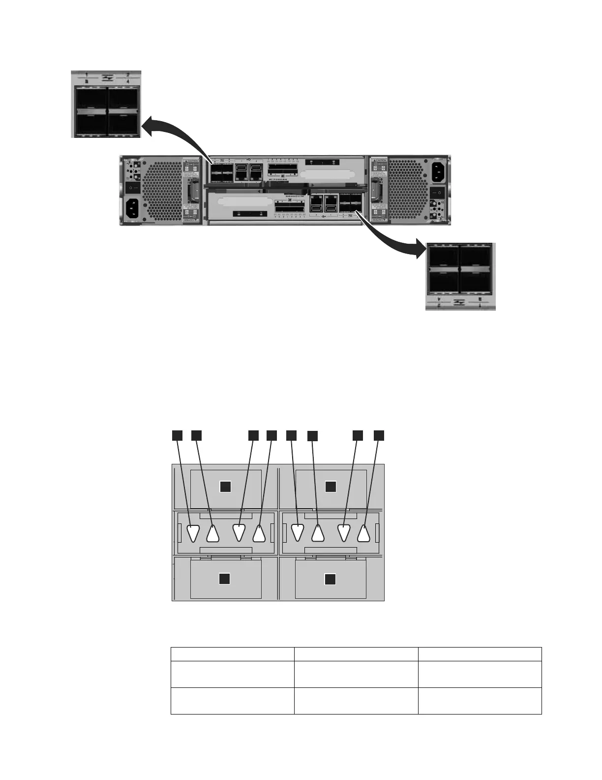
There are two green LEDs associated with each port: the speed LED and the link
activity LED. These LEDs are in the shape of a triangle. The LEDs are located in
between the two rows of the ports as shown in Figure 29. Figure 29 shows the
LEDs for the Fibre Channel ports on canister 1. Each LED points to the associated
port. The first and second LEDs in each set show the speed state, and the third
and fourth LEDs show the link state.
Table 19. Fibre Channel port LED locations on canister 1
Associated port LED location LED status
Port 3 3 First LED between ports 1
and 3 1
Speed
Port 1 1 Second LED between ports 1
and 3 2
Speed
svc00689
Figure 28. Fibre Channel ports on the node canisters
svc00685
5
6
7
8
1
2
4
3
1
2
3
4
Figure 29. LEDs on the Fibre Channel ports
Chapter 1. Storwize V7000 Unified hardware components 25

Table of Contents

Other manuals for IBM Storwize V7000 Unified

Questions and Answers:

Question and Answer IconNeed help?

Do you have a question about the IBM Storwize V7000 Unified and is the answer not in the manual?

IBM Storwize V7000 Unified Specifications

General IconGeneral
ModelIBM Storwize V7000 Unified
Storage TypeUnified Storage
RAID LevelsRAID 0, 1, 5, 6, 10
Form Factor2U
Drive Types SupportedSAS, SSD
Maximum Drives504
Network ProtocolsiSCSI, FC, FCoE
Drive Bays24 per enclosure
Host Interface8 Gb FC, 1 Gb/10 Gb iSCSI
File ProtocolsNFS, CIFS
Block ProtocolsiSCSI, Fibre Channel
TypeUnified Storage
Maximum Host Ports16
Operating System SupportVMware, Microsoft Windows, Linux, AIX
Data ServicesThin provisioning, replication
Power SupplyRedundant power supplies
Host Interfaces8 Gbps Fibre Channel, 10 Gbps iSCSI, 1 Gbps iSCSI

Related product manuals