EasyManuals Logo

IBM Storwize V7000 Unified Problem Determination Guide

IBM Storwize V7000 Unified
474 pages
To Next Page IconTo Next Page
To Previous Page IconTo Previous Page
Page #400 background imageLoading...
Page #400 background image
6. Remove the replacement host interface adapter 1 from its package.
Figure 118 on page 373 displays installing the host interface adapter.
7. Set the connecting edge of the replacement host interface adapter 3 on the
host interface adapter connector so that the connectors are aligned.
8. Ensure that the adapter is perpendicular to the canister main board so that the
small tab on the top of the bracket 2 is aligned with the alignment hole in
the top edge of the slot.
9. Maintain alignment while applying pressure to the top edge of the host
interface adapter opposite the connecting edge to push the host interface
adapter into the connector 4 and 5.
1
2
fab10038
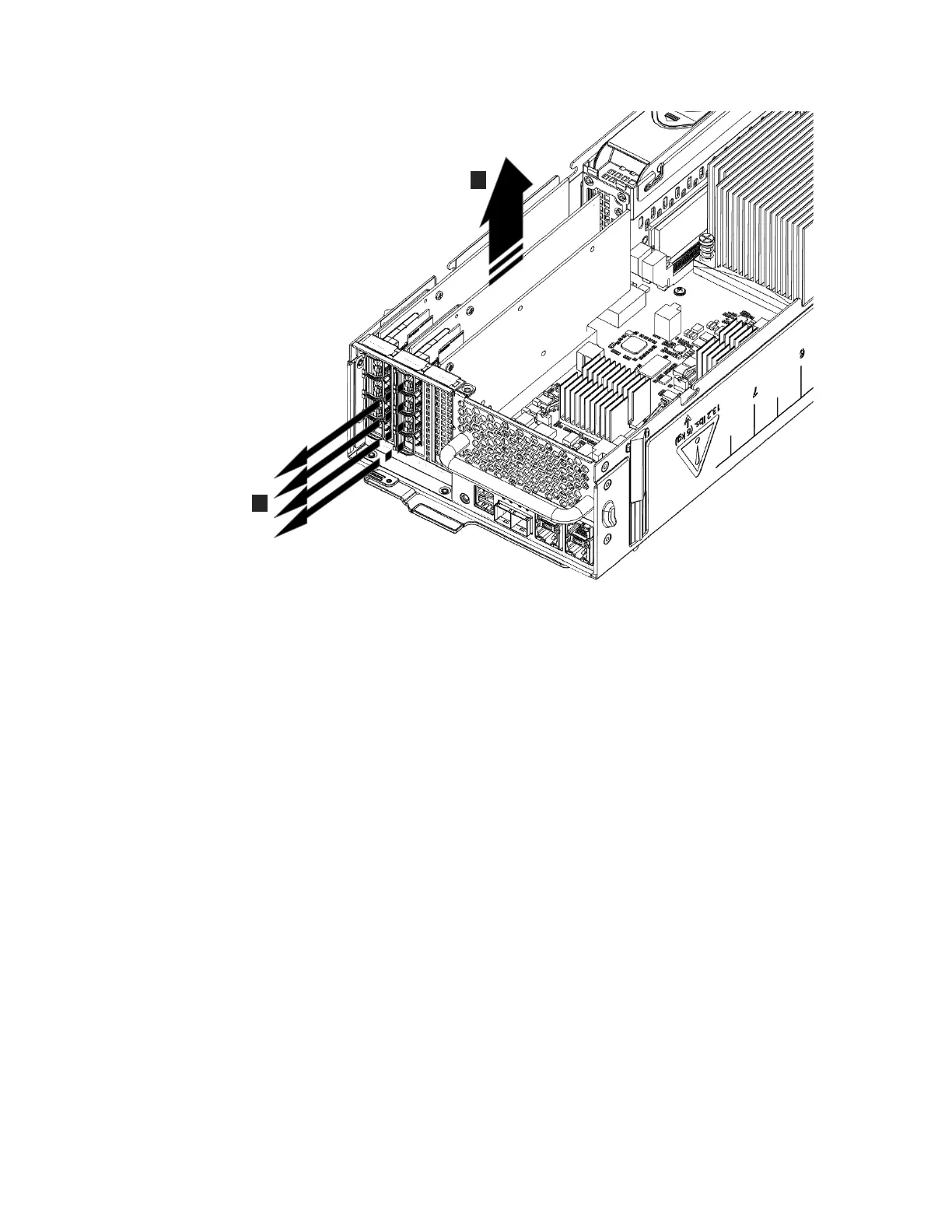
Figure 117. Removing the host interface adapter
372 Storwize V7000 Unified: Problem Determination Guide 2073-720

Table of Contents

Other manuals for IBM Storwize V7000 Unified

Questions and Answers:

Question and Answer IconNeed help?

Do you have a question about the IBM Storwize V7000 Unified and is the answer not in the manual?

IBM Storwize V7000 Unified Specifications

General IconGeneral
ModelIBM Storwize V7000 Unified
Storage TypeUnified Storage
RAID LevelsRAID 0, 1, 5, 6, 10
Form Factor2U
Drive Types SupportedSAS, SSD
Maximum Drives504
Network ProtocolsiSCSI, FC, FCoE
Drive Bays24 per enclosure
Host Interface8 Gb FC, 1 Gb/10 Gb iSCSI
File ProtocolsNFS, CIFS
Block ProtocolsiSCSI, Fibre Channel
TypeUnified Storage
Maximum Host Ports16
Operating System SupportVMware, Microsoft Windows, Linux, AIX
Data ServicesThin provisioning, replication
Power SupplyRedundant power supplies
Host Interfaces8 Gbps Fibre Channel, 10 Gbps iSCSI, 1 Gbps iSCSI

Related product manuals