Table 53. Components identified as customer replaceable units (CRUs) and field
replaceable units (FRUs) (continued)
Types of
replaceable
parts
Explanation of
each type of
replaceable part
Procedures categorized under each type of
replaceable part
Field replaceable
units (FRUs)
FRUs must be
installed only by
trained service
technicians.
“Installing the 240 VA safety cover” on page 128
“Removing a microprocessor and heat sink” on page
166
“Installing a microprocessor and heat sink” on page
170
“Removing and replacing the thermal grease” on
page 174
“Removing a heat-sink retention module” on page
176
“Installing a heat-sink retention module” on page
176
“Removing the system board” on page 177
“Installing the system board” on page 179
“Setting the machine serial number” on page 181
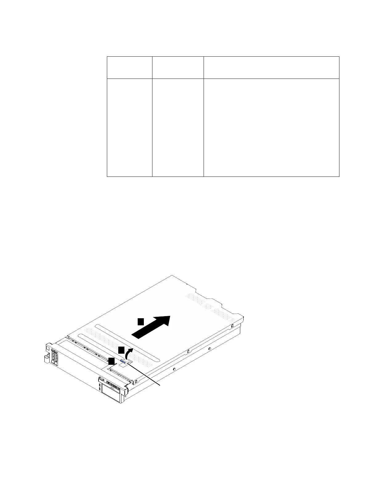
Removing the cover
The following procedure is for a Tier 1 customer replaceable unit (CRU).
Replacement of Tier 1 CRUs is your responsibility. If IBM installs a Tier 1 CRU at
your request, you will be charged for the installation. Service agreements can be
purchased so that you can ask IBM to replace these units.
About this task
To remove the cover, complete the following steps.
Procedure
1. Read the safety information that begins on page Safety and “Installation
guidelines” on page 94.
Cover-release
latch
v7000004
3
1
2
Figure 50. Removing the cover
Chapter 4. File module 123
 Loading...


