Procedure
1. Read the Safety information and “Installation guidelines” on page 94.
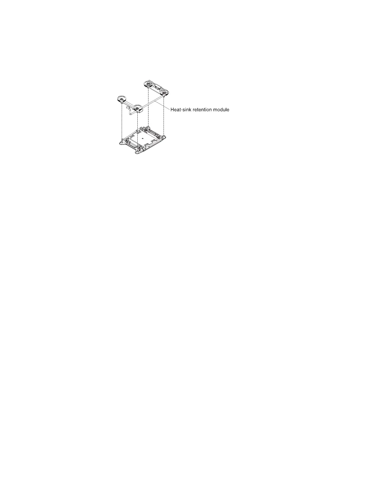
2. Align the retention module with the holes on the system board.
3. Use a screwdriver to reinstall the four screws.
4. Reinstall the microprocessor and heat sink (see “Installing a microprocessor and
heat sink” on page 170).
5. Reinstall the air baffle (see “Installing the air baffle” on page 138).
6. Install the cover (see “Installing the cover” on page 124).
7. Slide the file module into the rack.
8. Follow the steps at the end of the procedure “Removing a file module and
disconnecting power” on page 92 to reconnect the file module and resume its
use in the cluster.
Removing the system board
IBM authorized service providers can remove and replace the system board in the
file module. The following procedure is for a field replaceable unit (FRU). FRUs
must be installed only by trained service technicians.
About this task
To remove the system board, complete the following steps.
Procedure
1. Read the Safety information and “Installation guidelines” on page 94.
2. Follow the procedure in “Removing a file module and disconnecting power”
on page 92 to suspend the file module from the cluster and shut it down, and
then disconnect all power cords and external cables.
3. Pull the power supplies out of the rear of the file module, just enough to
disengage them from the file module.
4. Remove the file module cover (see “Removing the cover” on page 123).
5. Remove the riser-card assemblies with adapters (see “Removing a PCI
riser-card assembly” on page 141).
Attention: Place all removed components on a static-protective surface for
reinstallation.
6. Remove the 10 Gbps Ethernet adapter (see Removing a 10-Gbps Ethernet
adapter).
7. Remove the air baffle (see “Removing the air baffle” on page 137).
8. Remove all DIMMs, and place them on a static-protective surface for
reinstallation (see “Removing a memory module” on page 152).
Chapter 4. File module 177
 Loading...


