Table 7. Storwize V7000 Unified Gen1 model numbers
Machine
type/model Description
2076-112 Storwize V7000 Unified control enclosure for up to 12 3.5-inch (8.89
cm) drives
2076-124 Storwize V7000 Unified control enclosure for up to 24 2.5-inch (6.35
cm) drives
2076-312 Storwize V7000 Unified control enclosure for 3.5-inch drives (with two
10 Gbps iSCSI/FCoE Ethernet ports)
2076-324 Storwize V7000 Unified control enclosure for 2.5-inch drives (with two
10 Gbps iSCSI/FCoE Ethernet ports)
2076-212 Storwize V7000 Unified expansion enclosure for 3.5-inch drives
2076-224 Storwize V7000 Unified expansion enclosure for 2.5-inch drives
Storwize V7000 Unified Gen2 refers to the newer generation of enclosures in the
following table:
Table 8. Storwize V7000 Unified Gen2 model numbers
Machine
type/model Description
2076-524 Storwize V7000 Unified control enclosure, with up to 24 2.5-inch (6.35
cm) drives
2076-12F Storwize V7000 Unified expansion enclosure for up to 12 3.5-inch (8.89
cm) drives
2076-24F Storwize V7000 Unified expansion enclosure for 2.5-inch drives
Storwize V7000 Gen2 power supply units
Each Storwize V7000 Gen2 enclosure contains two power supply units.
Note: The power supply has no power switch. A power supply is active when a
power cord is connected to the power connector and to a power source.
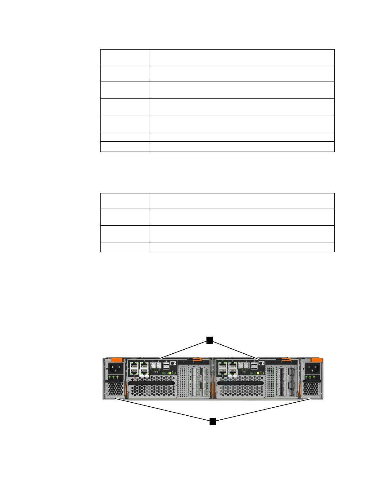
Figure 17 shows the rear view of a control enclosure and identifies the location of
the power supply units and node canisters.
▌1▐ Node canisters
Figure 17. Rear view of a Storwize V7000 Unified control enclosure
10 Storwize V7000 Unified: Problem Determination Guide 2073-720

 Loading...


