If an error occurs, view the light path diagnostics LEDs in the following order:
1. Look at the operator information panel on the front of the server.
If the information LED is lit, it indicates that information about a
suboptimal condition in the server is available in the IMM event log or in
the system event log.
If the system-error LED is lit, it indicates that an error has occurred; go to
step 2.
The following illustration shows the operator information panel on the front of
the file node.
Hard disk drive
activity LED (green)
Hard disk drive
status LED (amber)
Hard disk
drive bays
Rack
release
latch
Video
connector
USB 1
connector
USB 2
connector
Operator
information panel
CD/DVD
eject button
CD/DVD drive
activity LED
Rack
release
latch
CD/DVD drive
(optical drive)
Bay 11
Bay 0
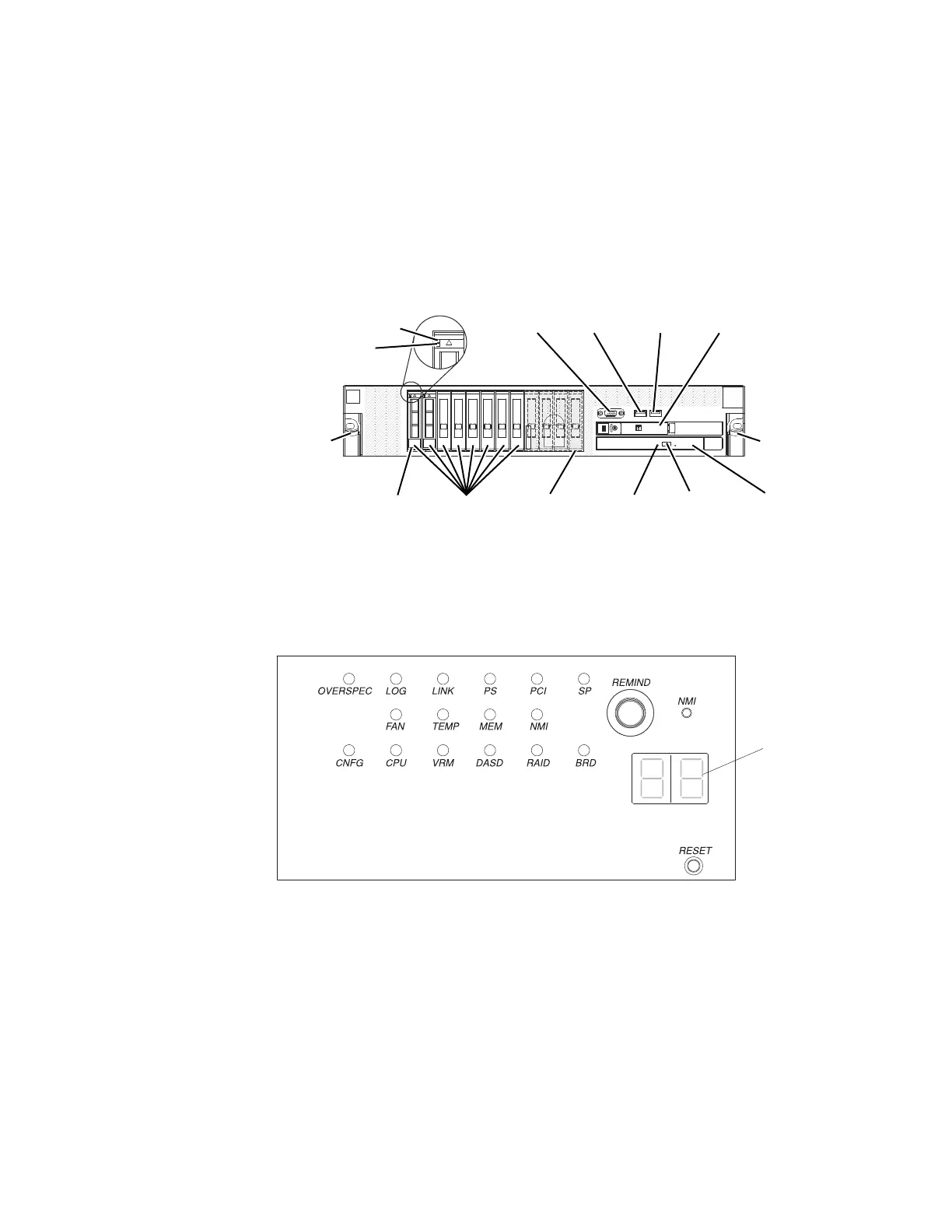
2. To view the light path diagnostics panel, slide the latch to the left on the front
of the operator information panel and pull the panel forward. This reveals the
light path diagnostics panel. Lit LEDs on this panel indicate the type of error
that has occurred.
The following illustration shows the light path diagnostics panel.
Note any LEDs that are lit, and then push the light path diagnostics panel back
into the server.
Note:
v Do not run the server for an extended period of time while the light path
diagnostics panel is pulled out of the server.
v Light path diagnostics LEDs remain lit only while the server is connected to
power.
Look at the system service label on the top of the server, which gives an
overview of internal components that correspond to the LEDs on the light path
diagnostics panel. This information and the information in Light path
diagnostics LEDs can often provide enough information to diagnose the error.
78 Storwize V7000 Unified: Problem Determination Guide 2073-720
 Loading...


