A-11
A-1List of Parameters
APPENDIX
- SV Series User’s Manual -
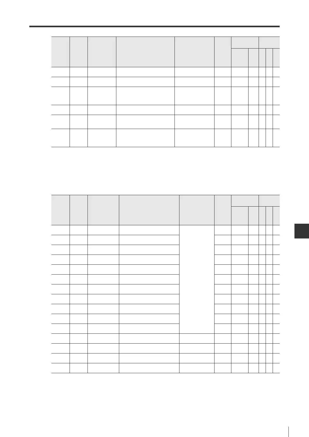
■I/O-related parameters
OTH_24 Special
*Motor less
encoder type
To set up encoder type for motor-
less test function.
0 : INC
1 : ABS
0
○
(00C.2)
○○○○
OTH_25 Special
*200V power
supply
To set up type of power supply
(AC/DC).
0 : AC
1 : DC
0
○
(001.2)
○○○○
OTH_26 Special
*Main circuit
voltage drop
To set up whether "main circuit
supply voltage low warning (971)"
is detected or not when main circuit
supply voltage is low.
0: Not detect
1: Warning
2: Warning and torque
limit
0
○
(008.1)
○○○○
OTH_27 Special
Trq lim at main
circuit vol drop
To set up torque limit when main
circuit supply voltage drops.
0 to 100(%) 50
○
(424)
○○○○
OTH_28 Special
Rel time for trq
lim at vol drop
To set up release time for torque
limit when main circuit supply
voltage drops.
0 to 1000(ms) 100
○
(425)
○○○○
OTH_29 Special
Instantaneous
powercut hold
time
To set up the instantaneous powercut
time for continuous operation when
instantaneous powercut occurs in main
circuit power supply.
20 to 1000(ms) 20
○
(509)
○○○○
Parameter
Categor
y
Parameter
name
*1
Description
Set value/Setting
unit
Default
value
Enable type
*2
Control
mode
ML-II
PLS
Position
Speed
Torque
*1 For parameters marked with "*", the power needs to be restarted after setup.
*2 ML-II is the short name for MECHATROLINK-II type and PLS the pulse/analog input type.
For MECHATROLINK-II, the number in the bracket is parameter number.
Parameter
Categor
y
Parameter
name
*1
Description
Set value/
Setting unit
Default
value
Enable type
*2
Control
mode
ML-II
PLS
Position
Speed
Torque
IO_01
Extend
*Input1 assignment
To set up the function of input terminal (IN1)
(20-pin) of I/O connector.
0: None
1 : SVON
2 : RESET
3 : PCN
4 : PTL
5 : NTL
6 : ST1/RS1
7 : ST2/RS2
8 : LSP
9 : LSN
10 : GAIN
11 : SPD1
12 : SPD2
13 : SPD3
14 : CSEL
15 : GEAR1
16 : GEAR2
17 : INHIBIT
18 : ZCLAMP
19 : SEN
11 -
○○○○
IO_02
Extend
*Input2 assignment
To set up the function of input terminal (IN2)
(21-pin) of I/O connector.
12 -
○○○○
IO_03
Extend
*Input3 assignment
To set up the function of input terminal (IN3)
(22-pin) of I/O connector.
19 -
○○○○
IO_04
Extend
*Input4 assignment
To set up the function of input terminal (IN4)
(23-pin) of I/O connector.
7-
○○○○
IO_05
Extend
*Input5 assignment
To set up the function of input terminal (IN5)
(24-pin) of I/O connector.
1-
○○○○
IO_06
Extend
*Input6 assignment
To set up the function of input terminal (IN6)
(41-pin) of I/O connector.
6-
○○○○
IO_07
Extend
*Input7 assignment
To set up the function of input terminal (IN7)
(42-pin) of I/O connector.
8-
○○○○
IO_08
Extend
*Input8 assignment
To set up the function of input terminal (IN8)
(43-pin) of I/O connector.
9-
○○○○
IO_09
Extend
*Input9 assignment
To set up the function of input terminal (IN9)
(44-pin) of I/O connector.
2-
○○○○
IO_10
Extend
*Input10 assignment
To set up the function of input terminal (IN10)
(45-pin) of I/O connector.
4-
○○○○
IO_11
Extend
*Input11 assignment
To set up the function of input terminal (IN11)
(46-pin) of I/O connector.
5-
○○○○
IO_12
Extend
*FSTOP polarity
To set up the function of input
terminal (FSTOP) (18-pin) of I/O connector.
0: N.O.
1: N.C.
1-
○○○○
IO_13
Extend
*Input 1 polarity
To set up the polarity of input terminal (IN1)
(20-pin) of I/O connector.
0: N.O.
1: N.C.
0-
○○○○
IO_14
Extend
*Input 2 polarity
To set up the polarity of input terminal (IN2)
(21-pin) of I/O connector.
0: N.O.
1: N.C.
0-
○○○○
IO_15
Extend
*Input 3 polarity
To set up the polarity of input terminal (IN3)
(22-pin) of I/O connector.
0: N.O.
1: N.C.
0-
○○○○
*1 For parameters marked with "*", the power needs to be restarted after setup.
*2 ML-II is the short name for MECHATROLINK-II type and PLS the pulse/analog input type.
For MECHATROLINK-II, the number in the bracket is parameter number.
 Loading...